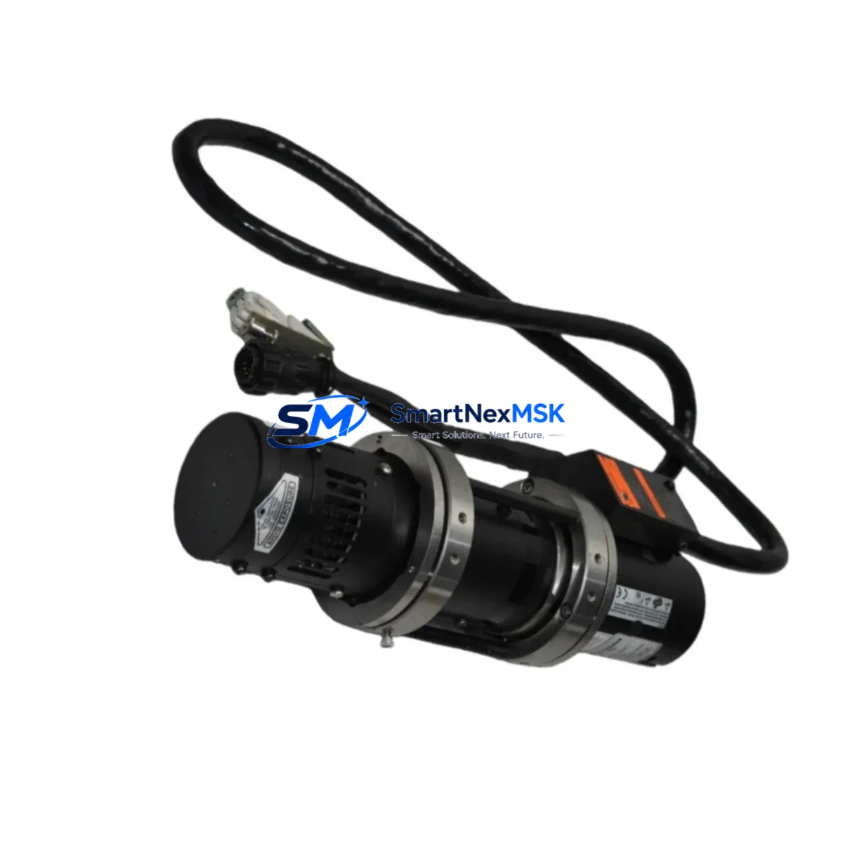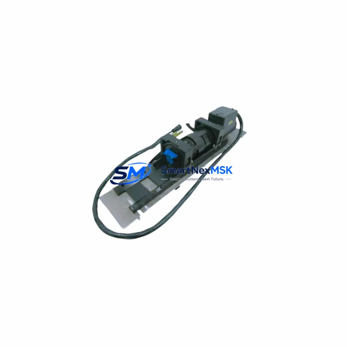
JDS UNIPHASE 2213-75SLRAMO72 Maintenance-Ready Spare for 2213 Series Automation
The JDS UNIPHASE 2213-75SLRAMO72 is a precision servo motor designed for continuous-duty industrial automation applications within the 2213 Series platform. For maintenance engineers managing aging motion control systems, unplanned servo motor failure is one of the highest-risk events in a production environment — capable of triggering multi-hour or multi-day downtime across an entire line. Stocking a verified, tested replacement unit of the 2213-75SLRAMO72 is the most direct mitigation strategy available.
This unit is sourced as an original spare, fully inspected prior to dispatch, and backed by a 12-month warranty. It is suitable for direct drop-in replacement in 2213 Series servo drive systems, with no firmware reconfiguration required in standard installations. Each unit undergoes pre-shipment functional verification to confirm encoder integrity, winding resistance, and mechanical shaft condition before leaving the warehouse.
Spare Maintenance Table
| Parameter | Specification / Detail |
|---|---|
| Part Number | 2213-75SLRAMO72 |
| Alternate SKU | 2213-75SLRAM072 |
| Brand | JDS UNIPHASE |
| Series | 2213 Series |
| Product Type | Servo Motor (Brushless DC) |
| Application | Industrial motion control, automation positioning, CNC auxiliary axis |
| Compatibility | 2213 Series servo drives and amplifiers; compatible encoder feedback interface |
| Mounting | Flange-mount; verify frame size against OEM mechanical drawing before installation |
| Feedback Type | Incremental encoder (verify pulse count with drive parameter settings) |
| Operating Environment | Industrial panel / machine cabinet; IP rating per OEM datasheet |
| Condition | Original spare — pre-shipment tested |
| Origin | United States |
| Warranty | 12 Months from date of shipment |
| Lead Time | In-stock units ship within 1–3 business days |
| Maintenance Recommendation | Inspect encoder cable, motor power connector, and drive amplifier card at time of replacement |
Maintenance Planning for Continuous Operation
When a 2213-75SLRAMO72 servo motor is flagged for replacement — whether during a scheduled shutdown, a predictive maintenance inspection, or an emergency fault response — experienced maintenance engineers know that the motor itself is rarely the only component requiring attention. A thorough site assessment at the time of replacement significantly reduces the probability of a repeat fault within the same maintenance cycle.
Begin by inspecting the servo drive amplifier paired to this motor. In 2213 Series systems, the amplifier card is responsible for current loop regulation; if the motor failed due to an overcurrent event, the amplifier’s output stage IGBTs may have sustained stress damage. Simultaneously, check the encoder feedback cable — a common failure point in high-vibration environments — and verify that the motor power cable connectors show no signs of arcing, insulation breakdown, or pin corrosion.
At the control cabinet level, inspect the 24VDC control power supply module that feeds the servo enable and brake release circuits. A marginal power supply can cause intermittent servo faults that are misdiagnosed as motor failures. If the system uses a safety relay module for STO (Safe Torque Off) or E-stop integration, verify its output contacts and response time have not degraded.
For systems with multiple axes, review the I/O module handling the servo ready and fault signals — particularly if the fault was accompanied by a PLC alarm. Faulty I/O channels can mask true fault sources. If the machine uses a fieldbus communication module (PROFIBUS, EtherCAT, or DeviceNet) for motion coordination, confirm that the node address and baud rate parameters are correctly retained after the drive replacement.
In older installations, it is also advisable to inspect the terminal block assemblies on the motor power and feedback circuits, as loose or oxidized terminals are a leading cause of intermittent servo errors. Where signal isolation is required between the servo drive and the PLC analog output, check the signal isolator module for drift or output clipping. Finally, if the machine includes an HMI panel displaying axis position or fault history, use it to review the fault log before clearing alarms — historical fault codes often reveal whether the motor failure was preceded by thermal warnings, encoder errors, or communication timeouts.
Proactive inspection of these surrounding components — power supplies, amplifier cards, encoder cables, I/O modules, communication nodes, terminal blocks, and safety relays — transforms a reactive motor swap into a comprehensive maintenance event that extends system uptime and reduces the frequency of future emergency callouts.
Site Replacement Workflow
Step 1 — Isolation & Lockout: De-energize the servo drive and apply LOTO (Lockout/Tagout) per site safety procedures. Allow the DC bus capacitors to fully discharge before opening the cabinet.
Step 2 — Documentation: Photograph the existing motor nameplate, encoder cable routing, and connector pinout before disconnection. Record the drive parameter file (motor ID, encoder resolution, current limits) from the HMI or programming terminal.
Step 3 — Mechanical Removal: Disconnect the motor power cable and encoder feedback cable. Remove the motor from its mounting flange, noting the shaft coupling alignment and any brake wiring if a holding brake is fitted.
Step 4 — Spare Verification: Confirm the replacement 2213-75SLRAMO72 nameplate data matches the removed unit. Verify encoder type and pulse count. Check shaft diameter and key dimensions against the coupling.
Step 5 — Installation: Mount the replacement motor, reconnect power and encoder cables, and torque all fasteners to specification. Restore the drive parameter file and verify motor ID settings match the new unit.
Step 6 — Commissioning: Perform a low-speed jog test to confirm encoder direction and feedback signal integrity. Check for drive fault codes. Gradually increase to operating speed and verify position accuracy and current draw are within normal range.
Step 7 — Documentation & Stock Update: Record the replacement in the maintenance log, update the spare parts inventory, and initiate a reorder for the consumed spare to maintain minimum stock levels.
This workflow is applicable whether replacing a like-for-like 2213-75SLRAMO72 or substituting from a compatible alternate SKU (2213-75SLRAM072). The structured approach minimizes commissioning time and ensures system compatibility is confirmed before returning the machine to production.
Spare Parts Support FAQ
Q1: What is the warranty coverage for the 2213-75SLRAMO72 spare?
All units are covered by a 12-month warranty from the date of shipment. The warranty covers manufacturing defects and verified functional failures under normal operating conditions. Each unit is pre-shipment tested for encoder signal integrity, winding continuity, and mechanical condition prior to dispatch.
Q2: How do I confirm compatibility before ordering?
Compatibility is confirmed by matching the full part number (2213-75SLRAMO72 or alternate 2213-75SLRAM072), the series designation (2213 Series), and the encoder feedback type against your existing drive parameter settings. If you have access to the OEM system documentation or the drive’s motor configuration file, share the motor ID and encoder resolution parameters with our technical team for pre-order verification.
Q3: What is the recommended spare parts stocking strategy for 2213 Series servo systems?
For production-critical systems, we recommend maintaining a minimum of one replacement 2213-75SLRAMO72 unit on-site, alongside a spare encoder feedback cable assembly and a spare servo drive amplifier card. For facilities operating multiple axes of the same model, a 10–15% spare ratio (one spare per 7–10 installed units) is a common industry benchmark. Long lead-time components such as the motor and amplifier should be prioritized in the spare parts budget.
Q4: Can this spare be used to replace older or discontinued variants in the 2213 Series?
The 2213-75SLRAMO72 is designed for direct replacement within the 2213 Series platform. For older or discontinued variants with minor suffix differences, our technical team can assist with cross-reference verification. In most cases, parameter adjustments within the servo drive (motor ID, encoder resolution, current rating) are sufficient to accommodate minor variant differences without mechanical modification.
© 2026 SMARTNEXMSK. All rights reserved.
Original Source: https://smartnexmsk.com
Contact: sales@smartnexmsk.com | +86 18259474341