Jetter JX6-BASIS-4 Spare for JX6 Series Automation: Spare Replacement & Downtime Risk Control
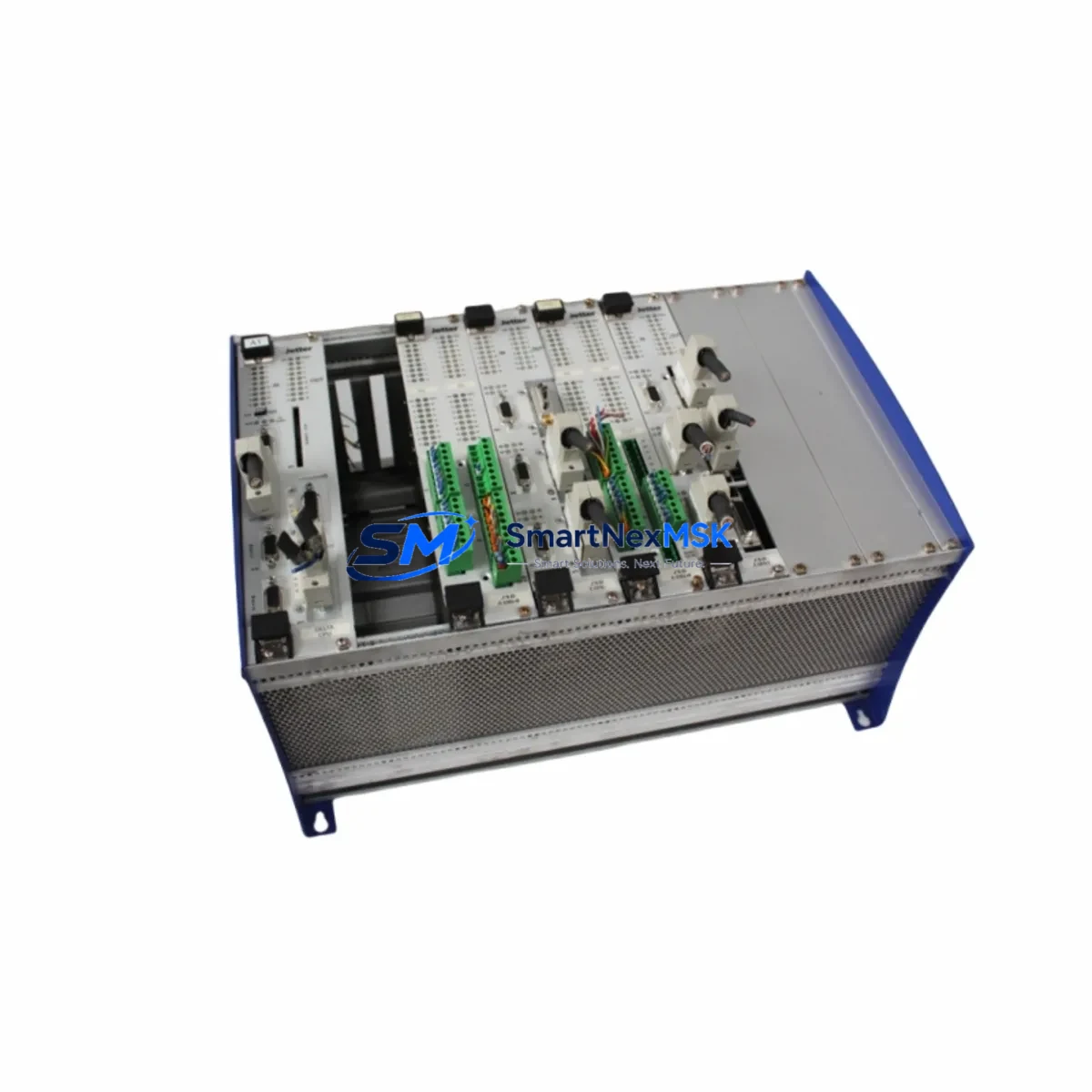
The Jetter JX6-BASIS-4 is the 4-slot CPU base unit at the heart of the JX6 Series modular PLC platform. In industrial automation environments — from machine tool control to packaging lines and process automation — this base unit serves as the structural and electrical backbone of the entire control cabinet rack. When the JX6-BASIS-4 fails or degrades, the entire PLC system goes offline. Maintaining a verified, tested spare on the shelf is not optional for facilities running continuous or semi-continuous production; it is a fundamental element of any credible maintenance strategy.
This listing supplies an original Jetter JX6-BASIS-4 base unit, sourced, inspected, and test-shipped to confirm functional integrity before dispatch. Each unit is covered by a 12-month warranty and is available for fast delivery to support emergency replacement and planned maintenance schedules alike.
Spare Maintenance Table
| Parameter | Specification / Detail |
|---|---|
| Part Number / SKU | JX6-BASIS-4 |
| Brand | Jetter AG |
| Series | JX6 Series Modular PLC |
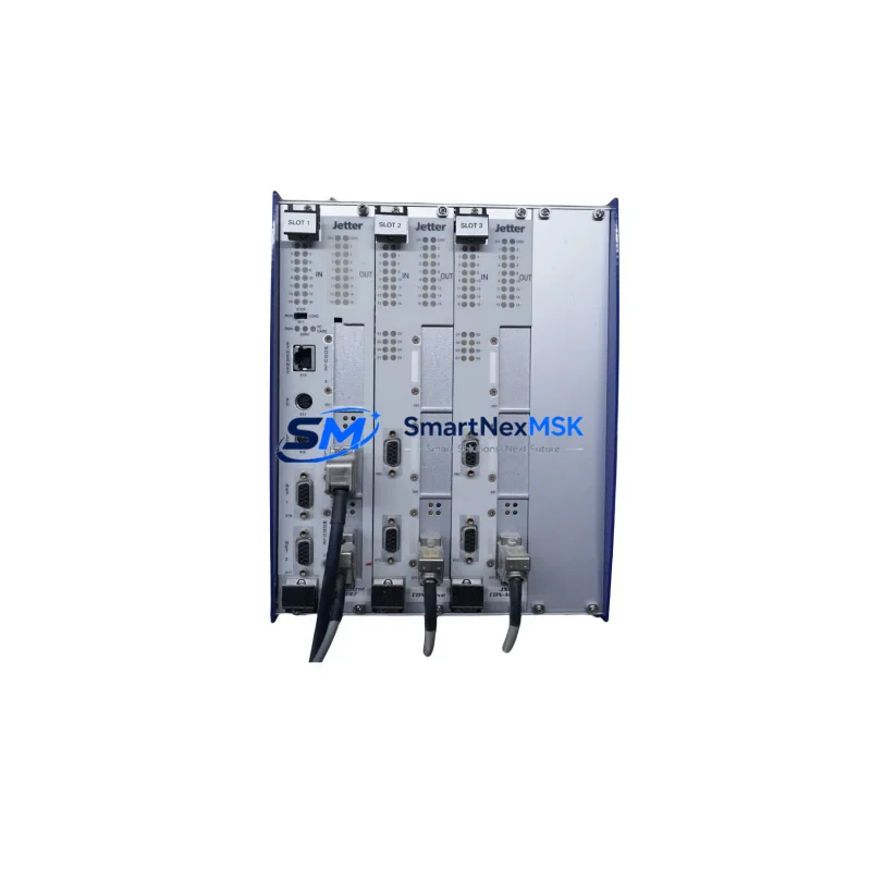
| Type | CPU Base Unit / Backplane (4-Slot) |
| Slot Capacity | 4 module slots (CPU + expansion) |
| Bus Interface | JX6 internal system bus |
| Power Supply Compatibility | JX6 Series 24 VDC power supply modules |
| Mounting | DIN rail / panel mount |
| Operating Temperature | 0 °C to +55 °C |
| Storage Temperature | -25 °C to +70 °C |
| Protection Class | IP20 (cabinet installation) |
| Origin | Germany |
| Compatibility | JX6-CPU, JX6-DIO, JX6-AIO, JX6-COM series modules |
| Application Environment | Industrial control cabinets, machine automation, process control |
| Maintenance Recommendation | Inspect bus connectors and slot contacts annually; replace if oxidation or mechanical wear is detected |
| Warranty | 12 Months |
| Condition | Original, tested before shipment |
Maintenance Planning for Continuous Operation
Replacing a JX6-BASIS-4 base unit in the field is rarely an isolated task. Maintenance engineers and procurement engineers planning a base unit swap should treat the replacement as an opportunity to audit the full JX6 rack assembly and associated electrical circuits. The following components are commonly inspected or replaced in the same maintenance window:
The JX6-CPU (central processing unit module) seats directly into the base unit and should be removed, inspected for connector pin condition, and reseated or replaced if the base unit shows signs of bus fault. Alongside the CPU, any installed JX6-DIO digital I/O modules should be checked for channel integrity — a degraded base unit bus can cause intermittent I/O faults that are misdiagnosed as field wiring problems. Similarly, JX6-AIO analog I/O modules are sensitive to bus signal quality and warrant re-verification after a base unit replacement.
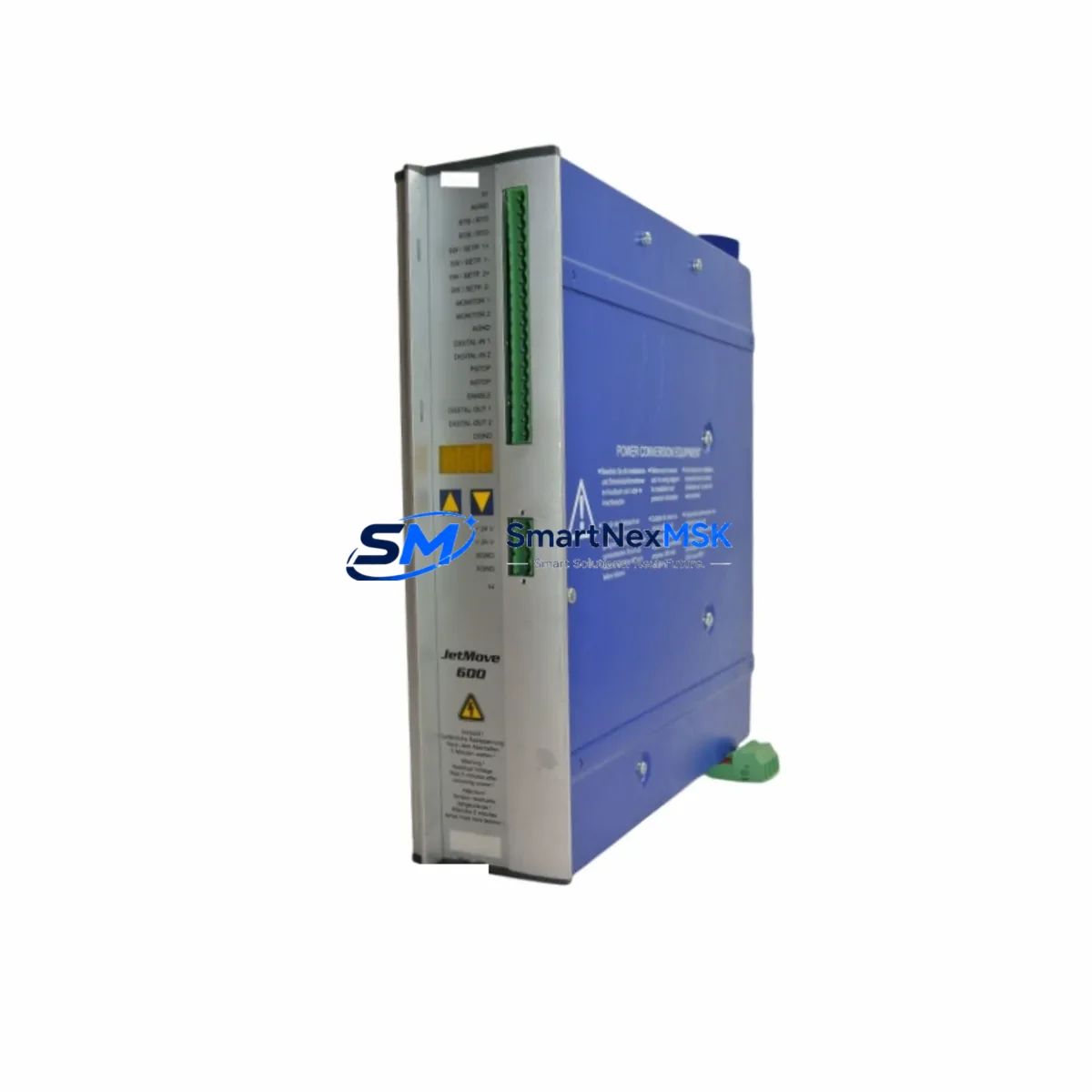
The JX6 Series 24 VDC power supply module feeds the entire rack; if the base unit failed due to power anomaly, the power supply module should be load-tested before the new base unit is commissioned. Upstream, the 24 VDC cabinet power supply (SMPS) and associated fuse or circuit breaker protection for the PLC rail should be verified for correct voltage and current capacity.
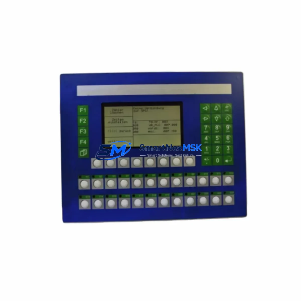
Communication continuity is equally critical. Any JX6-COM communication modules (PROFIBUS, CANopen, or Ethernet variants) installed in the rack must be re-initialized after a base unit swap, and their communication cables and connectors should be inspected for continuity and shielding integrity. If the system interfaces with a Jetter JX6-compatible HMI panel, the HMI communication link should be tested end-to-end after the replacement is complete.
For systems using signal isolation modules or signal conditioners between field sensors and the JX6 I/O modules, these should be checked for drift or damage — particularly if the original base unit failure was caused by a field-side surge. Terminal blocks and wiring ferrules on the I/O wiring side should be inspected for looseness or corrosion, and relay output modules or interposing relays in the same cabinet should be tested for contact resistance if they share the same control circuit.
Stocking a JX6-BASIS-4 spare alongside a JX6-CPU spare module and at least one set of JX6-DIO I/O modules provides a complete rack-level recovery kit that can restore a failed JX6 system to full operation within a single shift, minimizing unplanned downtime and its associated production losses.
Site Replacement Workflow
Step 1 — Isolation and Documentation: Before removing the failed JX6-BASIS-4, photograph the rack layout, module positions, and all wiring connections. Record the CPU firmware version and any module configuration data stored in the CPU. Power down the cabinet following your site LOTO (Lockout/Tagout) procedure and discharge any residual voltage on the power supply rail.
Step 2 — Module Removal: Remove all JX6 modules from the base unit slots in sequence, labeling each module with its slot position. Disconnect all I/O wiring from the module front connectors, keeping wiring harnesses bundled and labeled. Remove the base unit from the DIN rail or panel mounting.
Step 3 — Base Unit Inspection and Replacement: Inspect the replacement JX6-BASIS-4 for shipping damage and verify the bus connector condition. Mount the new base unit on the DIN rail, ensuring secure mechanical engagement. Reinstall all modules in their original slot positions and reconnect all I/O wiring per the documented layout.
Step 4 — Power-Up and Verification: Restore power and observe the CPU status LEDs for normal boot sequence. Verify all I/O module status indicators. Reload or confirm the CPU program and configuration. Test all I/O channels against the field device list before returning the system to automatic operation.
Step 5 — System Handover: Document the replacement in the maintenance log, including the date, replaced part number, and post-replacement test results. Update the spare parts inventory to trigger reorder of a replacement JX6-BASIS-4 for the next event.
This workflow is designed to minimize mean time to repair (MTTR) and ensure system compatibility is maintained throughout the replacement process. Using an original Jetter JX6-BASIS-4 eliminates firmware compatibility risks and ensures the bus timing and electrical characteristics match the installed JX6 module set.
Spare Parts Support FAQ
Q1: Is this JX6-BASIS-4 compatible with all JX6 Series CPU and I/O modules?
Yes. The JX6-BASIS-4 is the standard 4-slot base unit for the Jetter JX6 Series modular PLC platform and is compatible with all JX6-CPU, JX6-DIO, JX6-AIO, and JX6-COM series modules. If you are replacing an older JX6-BASIS-4 in an existing installation, the replacement is a direct fit with no firmware or hardware modification required.
Q2: What pre-shipment testing is performed on this spare unit?
Each JX6-BASIS-4 unit is functionally tested before dispatch to verify bus connector integrity, slot mechanical condition, and power rail continuity. Units that do not pass inspection are not shipped. A test report is available on request for critical spare applications.
Q3: How should I manage JX6-BASIS-4 inventory for a multi-machine facility?
For facilities operating three or more JX6-based control systems, we recommend maintaining at least one JX6-BASIS-4 base unit as a dedicated cold spare, stored in a dry, temperature-controlled environment. Pair this with a JX6-CPU spare and a set of the most common I/O module types used in your installation to enable full rack-level recovery without waiting for emergency procurement.
Q4: What does the 12-month warranty cover, and what is the process for a warranty claim?
The 12-month warranty covers manufacturing defects and functional failures under normal operating conditions. It does not cover damage caused by incorrect installation, overvoltage events, or physical mishandling. To initiate a warranty claim, contact sales@smartnexmsk.com with your order number, a description of the fault, and any available diagnostic data. Replacement or repair will be arranged promptly.
© 2026 SMARTNEXMSK. All rights reserved.
Original Source: https://smartnexmsk.com
Contact: sales@smartnexmsk.com | +86 18259474341