K-TEK M4A-AT Maintenance-Ready Spare for M4A Automation
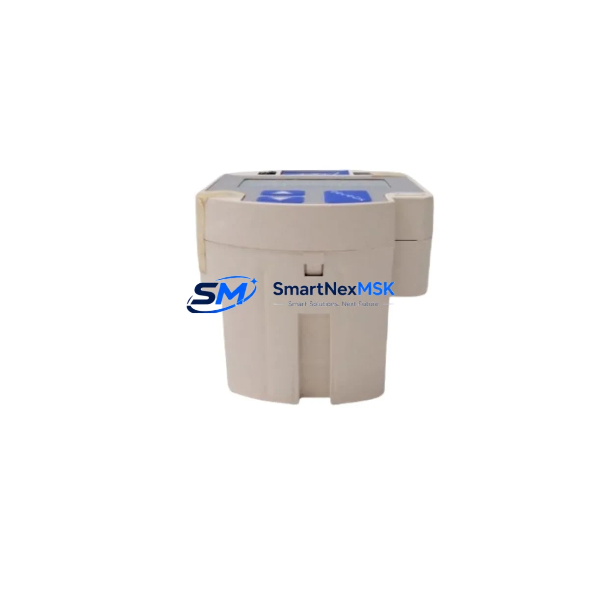
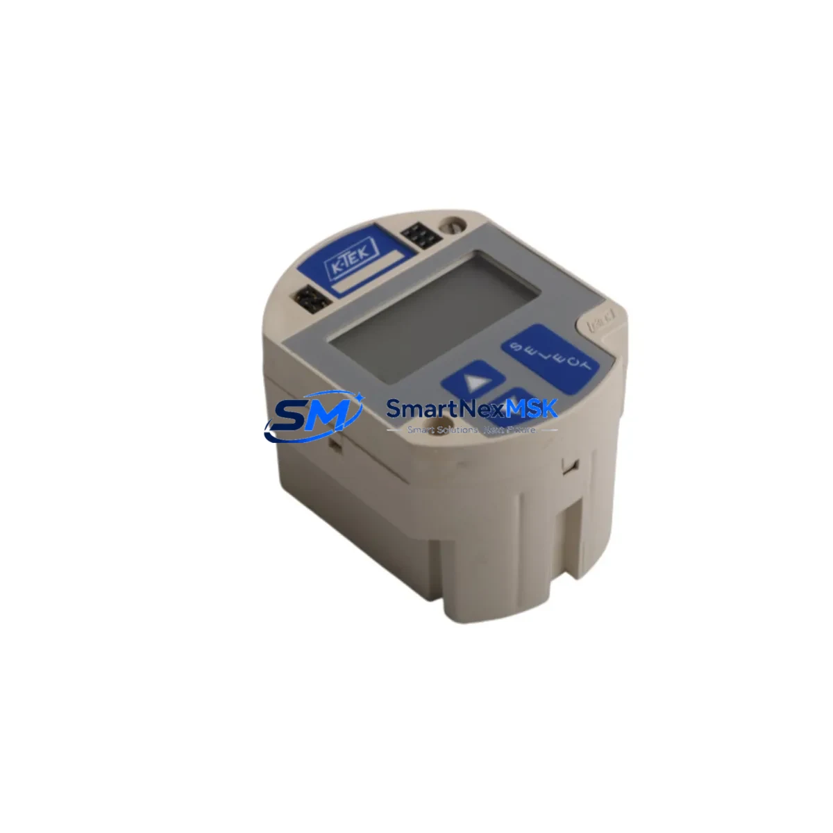
The K-TEK M4A-AT is a magnetostrictive level transmitter engineered for continuous, high-accuracy liquid level measurement in demanding industrial environments. As a maintenance-ready spare, the M4A-AT is the direct replacement for aging or failed units within the M4A Series platform, enabling maintenance engineers to restore process control with minimal disruption to production schedules. Whether you are managing a planned turnaround, responding to an unscheduled shutdown, or building a strategic spare parts inventory, the M4A-AT delivers the dimensional compatibility, signal integrity, and electrical specification match required for a confident, same-day swap.
The M4A-AT operates on a 4–20 mA HART output signal, making it fully compatible with existing DCS and PLC input cards without any signal conditioning changes. Its magnetostrictive sensing technology provides sub-millimeter resolution and is immune to foam, turbulence, and dielectric variation — characteristics that make it a preferred choice in chemical processing, oil and gas storage, water treatment, and power generation applications. The transmitter’s stainless steel housing and IP67 ingress protection rating ensure reliable performance in wet, corrosive, or high-humidity control cabinet environments.
For procurement engineers managing MRO budgets, the M4A-AT is available from stock with a 12-month warranty covering manufacturing defects and functional performance. Each unit undergoes pre-shipment functional testing, including zero/span verification and HART communication check, so field teams can install with confidence rather than spending valuable downtime on incoming inspection.
Spare Maintenance Table
| Parameter | Specification / Recommendation |
|---|---|
| SKU | M4A-AT |
| Brand / Series | K-TEK / M4A Series |
| Output Signal | 4–20 mA HART (two-wire) |
| Supply Voltage | 12–36 VDC (loop-powered) |
| Accuracy | ±0.05% Full Scale |
| Resolution | <0.1 mm |
| Process Connection | Flanged / threaded (M4A Series standard) |
| Housing / IP Rating | Stainless Steel / IP67 |
| Operating Temperature | –40°C to +85°C (electronics); process-dependent probe rating |
| Communication Protocol | HART Rev. 5/7 compatible |
| Compatibility | Direct replacement for M4A Series; compatible with standard 4–20 mA AI cards on Honeywell, Emerson, Siemens, and Yokogawa DCS/PLC platforms |
| Installation | Same mounting footprint as M4A Series predecessors; no pipe modification required |
| Pre-shipment Test | Zero/span calibration, HART communication verification, insulation resistance check |
| Warranty | 12 Months — covers manufacturing defects and functional performance |
Maintenance Planning for Continuous Operation
Effective maintenance planning for a level measurement loop extends well beyond the transmitter itself. When scheduling a replacement of the M4A-AT, maintenance engineers should treat the intervention as an opportunity to inspect and verify the condition of all components in the same electrical circuit and control loop.
Begin with the field wiring: check the two-wire loop cable for insulation degradation, moisture ingress at the cable gland, and terminal corrosion at the junction box. A corroded terminal block — even one that appears functional — can introduce loop resistance errors that shift the 4–20 mA signal by several microamps, causing false level readings at the DCS. Replace any suspect terminal strips with DIN-rail mounted screw terminals rated for the loop voltage and current range.
At the control cabinet, verify the 24 VDC loop power supply output voltage and ripple. An aging power supply module that delivers 22 V under load can push a two-wire transmitter below its minimum operating voltage, causing erratic output or complete signal loss. If the cabinet also powers other field instruments — such as pressure transmitters, flow meters, or temperature transmitters sharing the same 24 VDC bus — confirm that the total loop current budget is not exceeded.
The HART signal path deserves equal attention. If the site uses a HART multiplexer or a dedicated HART modem connected to a laptop for calibration, verify that the modem’s communication cable and the HART filter on the AI card are functioning correctly. Some older Honeywell TDC 3000 or Experion PKS AI cards have HART filters that degrade over time, preventing reliable HART communication even when the transmitter itself is healthy.
For sites running Emerson DeltaV or Fisher PROVOX systems, confirm that the AI card’s HART revision setting matches the transmitter’s HART revision. The M4A-AT supports HART Rev. 5 and Rev. 7; mismatched revision settings can prevent device description (DD) loading and block remote configuration from the DCS engineering station.
On the process side, inspect the float or probe assembly for scale buildup, mechanical damage, or float lodging. In applications involving viscous fluids or slurries, the probe guide tube may require cleaning before the new M4A-AT is installed. Also check the process isolation valve and the instrument manifold for seat leakage — a leaking isolation valve will prevent safe removal of the transmitter without a full process shutdown.
Finally, review the HMI faceplate configuration. After replacing the M4A-AT, confirm that the engineering unit, range (LRV/URV), and alarm setpoints displayed on the operator HMI screen match the new transmitter’s calibrated range. If the site uses a Wonderware InTouch or Ignition SCADA system, verify that the tag database reflects the correct instrument range so that the HMI bar graph and trend display are accurate from the first moment of operation.
Maintaining a minimum stock of one spare M4A-AT per critical level loop — alongside spare signal isolators, loop power supplies, and HART communication cables — is a proven strategy for reducing mean time to repair (MTTR) and protecting production continuity.
Site Replacement Workflow
A structured site replacement workflow minimizes downtime and eliminates the risk of introducing new faults during the swap. Follow these steps when replacing an M4A-AT in service:
1. Pre-work preparation: Obtain the loop drawing and instrument data sheet for the existing M4A-AT. Confirm the calibrated range (LRV/URV), process connection size, probe length, and output signal type. Verify that the replacement unit’s configuration matches these parameters before leaving the warehouse. Pre-configure the new M4A-AT using a HART communicator or laptop with the appropriate device description file loaded.
2. Loop isolation and process isolation: Place the DCS AI channel in manual mode or force the output to a safe value to prevent false process trips during the swap. Close the process isolation valve and depressurize or drain the instrument chamber as required by site safety procedures. Lock out and tag out (LOTO) the loop power supply at the marshalling cabinet.
3. Removal of the failed unit: Disconnect the field wiring at the transmitter head, noting the polarity and terminal assignments. Remove the transmitter from the process connection. Inspect the process connection threads or flange face for damage and clean as necessary.
4. Installation of the M4A-AT spare: Install the new transmitter, applying appropriate thread sealant or a new flange gasket. Reconnect the field wiring, observing correct polarity. Restore loop power and verify that the transmitter powers up and outputs a valid 4–20 mA signal corresponding to the current process level.
5. Functional verification: Use a HART communicator to confirm device identity, firmware version, and configured range. Perform a zero/span check if process conditions allow. Compare the transmitter output against an independent level reference (sight glass, radar level gauge, or manual dip measurement) to confirm accuracy. Return the DCS AI channel to automatic mode and verify that the HMI display updates correctly.
6. Documentation: Record the replacement in the site maintenance management system (CMMS), including the old unit’s serial number, failure mode, and the new unit’s serial number and calibration date. Update the instrument index and spare parts inventory accordingly.
Spare Parts Support FAQ
Q1: Is the M4A-AT a direct drop-in replacement for all M4A Series transmitters?
The M4A-AT shares the same mechanical footprint, process connection dimensions, and 4–20 mA HART output as the standard M4A Series platform, making it a direct replacement in the vast majority of applications. However, probe length is application-specific — confirm the probe length of the unit being replaced before ordering to ensure the new transmitter covers the full measurement range of your vessel or tank.
Q2: What compatibility verification should I perform before installation?
Verify the supply voltage range (12–36 VDC loop-powered), the HART revision supported by your DCS AI card, and the process connection type (flanged or threaded). If your DCS uses a device description (DD) library, confirm that the M4A-AT DD file is available for your HART revision. Contact our technical team with your DCS model and AI card part number if you need assistance with DD file compatibility.
Q3: How is the M4A-AT tested before shipment?
Every M4A-AT unit is tested prior to shipment. Testing includes power-up verification, zero and span calibration check against a traceable reference, HART communication test (device identification and variable read), and insulation resistance measurement. A test report is available upon request and can be included with the shipment documentation for your incoming inspection records.
Q4: What does the 12-month warranty cover, and how is a warranty claim handled?
The 12-month warranty covers manufacturing defects and functional performance failures under normal operating conditions. It does not cover damage caused by incorrect installation, overpressure, chemical attack beyond the rated wetted materials, or electrical overvoltage. To initiate a warranty claim, contact sales@smartnexmsk.com with the unit serial number, purchase order reference, and a description of the failure. We will arrange return shipping and provide a replacement or repair within an agreed lead time.
© 2026 SMARTNEXMSK. All rights reserved.
Original Source: https://smartnexmsk.com
Contact: sales@smartnexmsk.com | +86 18259474341