KONTRON CP6000 Retrofit-Ready CPU Module for CompactPCI Serial Control Systems
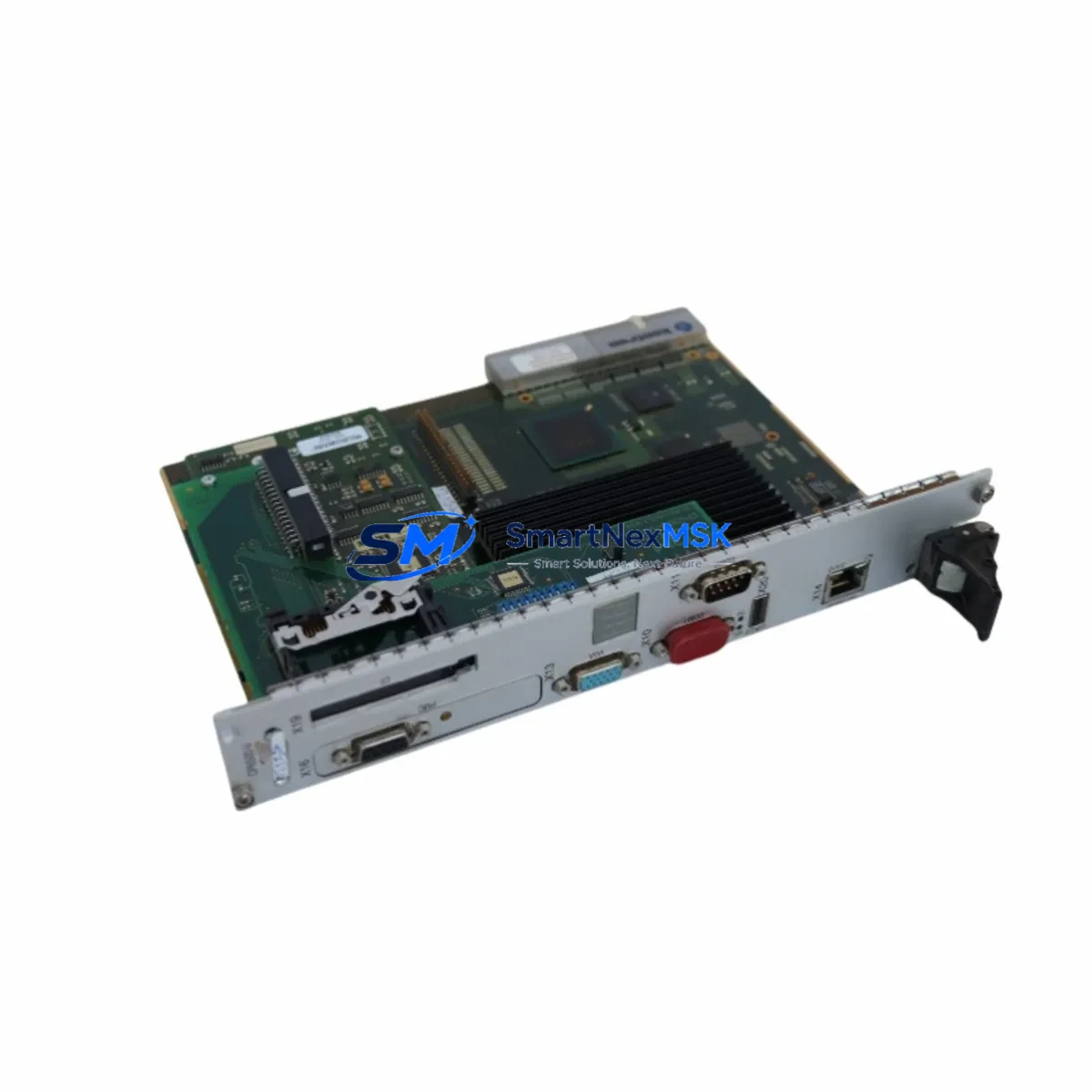
The KONTRON CP6000 is a high-performance CompactPCI Serial (CPCI-S.0) processor module engineered for seamless integration into legacy and modern industrial control architectures. As automation facilities face increasing pressure to modernize aging control infrastructure without full system overhauls, the CP6000 delivers a proven, drop-in upgrade path for engineers managing CompactPCI Serial backplanes, multi-slot chassis, and distributed I/O environments. Whether you are replacing an end-of-life CPU board, migrating from an older PICMG 2.0 parallel bus platform, or expanding processing capacity within an existing 19-inch rack enclosure, the CP6000 provides the compatibility, reliability, and long-term supply assurance that industrial retrofit projects demand.
Designed to KONTRON’s industrial-grade standards, the CP6000 supports the CompactPCI Serial system architecture with a PCIe-based backplane interface, enabling high-bandwidth communication between the system controller slot and peripheral slots populated with I/O modules, communication modules, and power supply units. Its robust thermal design and extended temperature tolerance make it suitable for deployment in control cabinets, machine rooms, and harsh industrial environments where continuous 24/7 operation is required.
Upgrade Compatibility Table
| Parameter | Details |
|---|---|
| Form Factor | CompactPCI Serial (CPCI-S.0), 3U / 6U compatible |
| Backplane Interface | PCIe x1 / x4 per PICMG CPCI-S.0 specification |
| System Slot | System Controller (Slot 1) — single system controller per segment |
| Peripheral Slot Compatibility | Compatible with CPCI-S.0 peripheral I/O, communication, and power modules |
| Legacy Migration | Replaces PICMG 2.0 parallel-bus CPU boards with adapter backplane or chassis swap |
| Communication Compatibility | Ethernet (GbE), USB 3.0, SATA; supports PROFINET, EtherNet/IP via software stack |
| OS Support | VxWorks, Linux (PREEMPT_RT), Windows Embedded Standard 7/10 |
| Installation Requirement | Hot-swap capable chassis required for live insertion; standard chassis requires power-down |
| Retrofit Recommendation | Verify chassis slot keying, backplane revision, and power rail capacity before installation |
| Commissioning Focus | Module address assignment, BIOS/firmware update, OS image restore, I/O driver reload |
| Warranty | 12-Month Warranty — covers manufacturing defects, functional failure under normal operating conditions |
Retrofit Planning for Existing Automation Systems
A successful CP6000 retrofit begins well before the module arrives on-site. Engineers must audit the existing chassis — typically a KONTRON or Schroff CompactPCI Serial chassis with 3U or 6U slots — to confirm the backplane revision supports the CPCI-S.0 PCIe interface. Older chassis built to the PICMG 2.0 parallel-bus standard are not directly compatible and will require either a backplane replacement or a hybrid chassis that bridges both form factors.
Power supply capacity is a critical pre-installation checkpoint. The CP6000 draws from the chassis power supply unit (PSU), and systems that previously ran lower-power CPU boards may need a PSU upgrade to accommodate the CP6000’s power envelope alongside co-installed peripheral modules such as KONTRON CP6001 or CP6002 I/O expansion boards. Verify that the combined load of all populated slots — including communication modules, digital I/O modules, and analog I/O modules — does not exceed the PSU’s rated output on the +3.3V, +5V, and +12V rails.
Terminal wiring and field I/O connections are typically unaffected by a CPU module swap, as these terminate on the peripheral I/O modules rather than the processor board itself. However, engineers should document all terminal assignments on modules such as KONTRON CP6010 digital input/output boards or third-party CPCI-S.0 analog modules before beginning the retrofit, as module address reassignment during commissioning can shift I/O mapping if the new CPU initializes the backplane in a different enumeration order.
Communication link continuity is another key concern. If the existing system uses PROFINET or EtherNet/IP for PLC-to-HMI communication — for example, connecting to a SIMATIC HMI panel or a Weintek cMT series touchscreen — the CP6000’s GbE ports must be configured with the same IP addressing scheme and protocol stack as the outgoing CPU. In systems where the legacy CPU hosted a proprietary communication protocol adapter, a KONTRON CP6030 or equivalent communication module may need to be retained or replaced in parallel to maintain fieldbus continuity during the cutover window.
For systems that include a KONTRON CP6020 or similar SATA storage module for program and data retention, verify that the CP6000’s SATA interface is compatible with the existing storage module’s connector and transfer rate. Program images, PLC logic files, and HMI screen packages should be backed up to an external medium before the retrofit begins. If the control system uses a programming cable — such as a USB-to-serial adapter or a dedicated JTAG/UART debug cable — confirm that the CP6000’s debug interface pinout matches the existing programming environment to avoid delays during post-installation commissioning.
Finally, rack and cabinet layout should be reviewed. The CP6000’s front panel connectors, LED indicators, and handle ejector mechanism must align with the chassis front panel cutout. In 19-inch control cabinet installations, ensure that cable management, cooling airflow, and EMC shielding provisions are maintained after the module swap to preserve CE and UL compliance of the overall control panel assembly.
Downtime Control During System Migration
Minimizing unplanned downtime is the primary operational constraint in any live production retrofit. For CP6000 installations, the recommended approach is a staged cutover: prepare the replacement module off-line, pre-load the OS image and application software, configure network parameters, and perform a bench-level functional test before bringing the module to the production floor. This pre-commissioning step can reduce on-site installation time to under two hours for experienced engineers.
Where the chassis supports hot-swap operation per the CPCI-S.0 specification, the CP6000 can be inserted into a powered chassis without a full system shutdown, provided the application software and OS are designed to handle dynamic module insertion. In non-hot-swap environments, a controlled shutdown sequence should be followed: save all active program states, archive HMI alarm logs, issue a graceful stop command to all connected field devices, and power down the chassis before extracting the legacy CPU board.
Original program logic should be preserved by exporting the PLC project file from the engineering workstation prior to the retrofit. If the legacy CPU stored the program in onboard flash or battery-backed SRAM, use the programming software’s upload function to retrieve the latest runtime image before powering down. After installing the CP6000, restore the program image, verify I/O channel mapping against the pre-retrofit documentation, and perform a controlled test run with field devices in manual mode before returning the system to automatic operation. This sequence protects production continuity and ensures that the HMI display, alarm thresholds, and interlock logic remain consistent with the pre-retrofit configuration.
Retrofit Support FAQ
Q1: Is the KONTRON CP6000 a direct drop-in replacement for older CompactPCI (PICMG 2.0) CPU boards?
The CP6000 is designed for CompactPCI Serial (CPCI-S.0) chassis and is not pin-compatible with legacy PICMG 2.0 parallel-bus backplanes. A chassis or backplane upgrade is required when migrating from PICMG 2.0 systems. For hybrid environments, consult KONTRON’s migration guide or contact our technical team to confirm compatibility before ordering.
Q2: What commissioning steps are required after installing the CP6000?
After physical installation, the commissioning sequence includes: BIOS/firmware verification, OS image restoration, network interface configuration (IP address, subnet, gateway), I/O driver installation, module address assignment on the backplane, PLC program upload, HMI communication link test, and a supervised test run in manual mode. All steps should be documented in the site commissioning record.
Q3: Does the 12-month warranty cover field-installed units?
Yes. The 12-month warranty covers manufacturing defects and functional failures under normal operating conditions from the date of shipment. Warranty claims require the original order reference and a fault description. Units showing evidence of physical damage, incorrect installation voltage, or unauthorized modification are excluded from warranty coverage.
Q4: Can you supply the CP6000 with pre-tested firmware and a factory acceptance test (FAT) report?
Yes. All units undergo functional testing prior to shipment. A factory test report confirming power-on self-test (POST) completion, interface verification, and burn-in results is available upon request. Pre-loading of specific OS images or firmware versions can be arranged for volume orders — contact sales@smartnexmsk.com to discuss project-specific requirements.
© 2026 SMARTNEXMSK. All rights reserved.
Original Source: https://smartnexmsk.com
Contact: sales@smartnexmsk.com | +86 18259474341