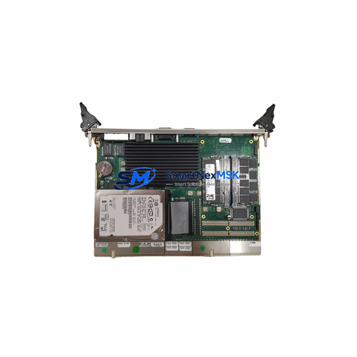
KONTRON CP6500-V Maintenance-Ready Spare for CP6500 Series Automation
Unplanned downtime in CompactPCI-based control systems is one of the most costly disruptions in industrial automation environments. The KONTRON CP6500-V is a 6U CompactPCI Single Board Computer (SBC) designed for high-availability embedded computing applications across manufacturing, transportation, defense, and process automation sectors. Maintaining a verified spare of the CP6500-V in your on-site or warehouse inventory is a proven strategy for rapid fault recovery, minimizing mean time to repair (MTTR), and extending the operational life of CP6500 Series chassis installations.
This listing provides a maintenance-ready, original KONTRON CP6500-V spare — sourced, inspected, and dispatched with full functional verification. Each unit is tested prior to shipment and backed by a 12-month warranty, giving maintenance engineers and procurement teams the confidence to stock this component as a long-term replacement asset.
Whether you are executing a planned shutdown inspection, responding to an unexpected board failure, or building out a structured spare parts inventory for a legacy CP6500 Series rack, the CP6500-V can be integrated directly into your existing backplane without system reconfiguration — provided BIOS settings, OS image, and I/O mapping are validated against your site configuration before hot-swap or cold-swap procedures begin.
Spare Maintenance Table
| Parameter | Specification / Recommendation |
|---|---|
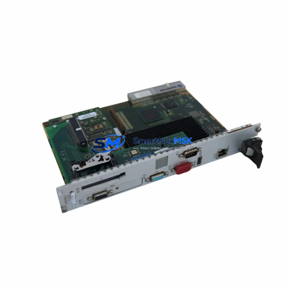
| Part Number | CP6500-V |
| Brand | KONTRON |
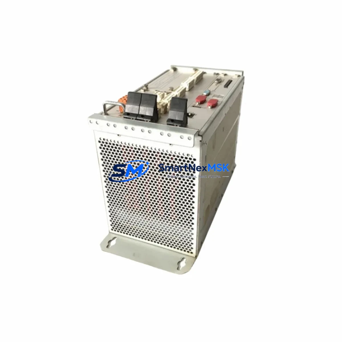
| Form Factor | 6U CompactPCI (PICMG 2.0) |
| Series Compatibility | CP6500 Series CompactPCI Chassis |
| Origin | Germany (DE) |
| Product Type | Single Board Computer (SBC) |
| Application Environment | Industrial automation, embedded control, transportation, defense |
| Installation Type | Cold-swap / Hot-swap (chassis-dependent) |
| Pre-shipment Testing | Full functional verification performed |
| Warranty | 12 Months |
| Maintenance Recommendation | Inspect backplane connectors, power rails, and I/O mapping before installation |
| Compatibility Verification | Confirm BIOS revision, OS image, and slot addressing with site documentation |
| Lead Time | In-stock; ships within 1–3 business days |
| Long-term Supply | Available for repeat procurement; suitable for multi-site spare pooling |
Maintenance Planning for Continuous Operation
When a CP6500-V board failure is identified during routine control cabinet inspection or fault diagnostics, the replacement procedure should not be limited to swapping the SBC alone. Experienced maintenance engineers understand that a board-level fault in a CompactPCI system is frequently accompanied by — or caused by — degradation in adjacent components. A structured inspection of the following elements is strongly recommended before and after CP6500-V replacement:
- CP6500 Series Backplane: Inspect all J1/J2 connector pins for oxidation, mechanical damage, or intermittent contact. A faulty backplane slot can damage a replacement SBC within hours of installation.
- CompactPCI Power Supply Module: Verify that the +5V, +3.3V, and +12V rails are within tolerance using a calibrated multimeter or power analyzer. Undervoltage conditions are a leading cause of SBC instability and premature failure.
- System Slot Power Filter Capacitors: On aging CP6500 chassis, electrolytic capacitors on the power distribution board may exhibit increased ESR. Replace proactively during planned maintenance windows.
- CompactPCI Peripheral Boards (I/O Modules): Any CP6500-compatible I/O boards installed in adjacent slots — such as serial communication cards, digital I/O modules, or analog signal acquisition boards — should be reseated and tested after SBC replacement to confirm bus integrity.
- Ethernet and Serial Communication Modules: If the CP6500-V interfaces with PROFIBUS, CANbus, or Ethernet-based field devices, verify that communication module firmware versions remain compatible with the replacement board’s driver stack.
- Signal Isolation Modules: In process automation environments, signal isolators protecting analog inputs (4–20 mA loops, thermocouple inputs) should be inspected for drift or calibration loss, particularly if the original board failure was caused by a transient overvoltage event.
- Terminal Blocks and Field Wiring: Inspect all terminal block connections on associated I/O panels for loose conductors, corrosion, or thermal discoloration — indicators of high-resistance joints that can introduce noise into signal lines.
- Fuse and Circuit Protection: Replace any blown or suspect fuses in the control cabinet power distribution section. Document fuse ratings and verify they match the original design specification.
- HMI Communication Link: If the CP6500-V drives or communicates with an operator panel or HMI, re-establish and test the communication link (RS-232, Ethernet, or proprietary protocol) after board replacement to confirm display and control functionality.
- UPS / Battery Backup Module: Test the uninterruptible power supply serving the CompactPCI rack. A weakened UPS battery may have contributed to the original board failure during a power event and should be replaced or load-tested.
Stocking the CP6500-V alongside these associated components in a structured spare parts kit significantly reduces the diagnostic and procurement time during emergency maintenance events, enabling same-shift fault recovery in most scenarios.
Site Replacement Workflow
The CP6500-V is a direct replacement for the original KONTRON CP6500-V installed in CP6500 Series 6U CompactPCI chassis. The following workflow is recommended for site engineers performing the replacement:
- Pre-replacement documentation: Record the current BIOS version, boot device configuration, IP address assignments, and any custom BIOS settings from the outgoing board before powering down the system.
- Safe power-down: Follow your site’s lockout/tagout (LOTO) procedure. Power down the CompactPCI chassis completely unless the chassis supports hot-swap on the target slot.
- Board extraction: Use the ejector handles to disengage the CP6500-V from the backplane. Avoid applying lateral force to the PCB edge. Store the removed board in an ESD-safe bag for return or failure analysis.
- Spare board preparation: Confirm the replacement CP6500-V firmware and BIOS revision. Apply any required configuration settings before installation where possible.
- Installation and seating: Insert the replacement board into the correct system slot, ensuring full engagement with the J1/J2 backplane connectors. Secure the front panel retaining screws to the specified torque.
- Power-up and POST verification: Apply power and observe the POST sequence. Confirm that all installed peripheral boards are recognized and that no fault LEDs are active.
- Functional test: Execute a site-specific functional test covering I/O response, communication link status, and application software startup. Document the test results and update the maintenance log.
- Return to service: Once all checks pass, return the system to normal operation and notify the operations team. Update the spare parts inventory record to reflect the consumed unit and initiate replenishment procurement.
This workflow is applicable to both emergency replacements and planned maintenance scenarios. For legacy CP6500 Series installations where the original board is no longer available through the OEM, the CP6500-V spare sourced through our inventory provides a validated, warranty-backed alternative that maintains full system compatibility without requiring chassis or software modifications.
Spare Parts Support FAQ
Q1: Is this CP6500-V spare compatible with all CP6500 Series chassis configurations?
The CP6500-V is designed for use in KONTRON CP6500 Series 6U CompactPCI chassis conforming to PICMG 2.0. Compatibility with specific chassis configurations — including slot addressing, power budget, and peripheral board combinations — should be verified against your site’s system documentation before installation. Our technical team can assist with compatibility confirmation prior to order.
Q2: What pre-shipment testing is performed on each CP6500-V unit?
Each CP6500-V spare undergoes full functional verification prior to dispatch, including power-on self-test (POST) completion, memory integrity check, and interface port validation. Units that do not pass all test criteria are not dispatched. A test report is available upon request for quality-critical procurement processes.
Q3: How should the CP6500-V be stored if it is purchased as a long-term inventory spare?
Store the CP6500-V in its original ESD-safe packaging in a dry, temperature-controlled environment (recommended: 10–35°C, relative humidity below 70%, non-condensing). Avoid storage near strong electromagnetic fields or chemical vapors. Inspect the unit annually and perform a bench power-on test every 12–18 months to confirm readiness. The 12-month warranty period begins from the date of shipment.
Q4: What is the lead time and can multiple units be ordered for multi-site spare pooling?
In-stock units ship within 1–3 business days. For multi-site spare pooling or volume procurement, please contact our sales team directly to confirm available quantity, pricing, and consolidated shipment options. Long-term supply agreements for critical spare components are supported.
© 2026 SMARTNEXMSK. All rights reserved.
Original Source: https://smartnexmsk.com
Contact: sales@smartnexmsk.com | +86 18259474341