KUKA C26D00 Retrofit-Ready Servo Motor for 1FK7 Control Systems
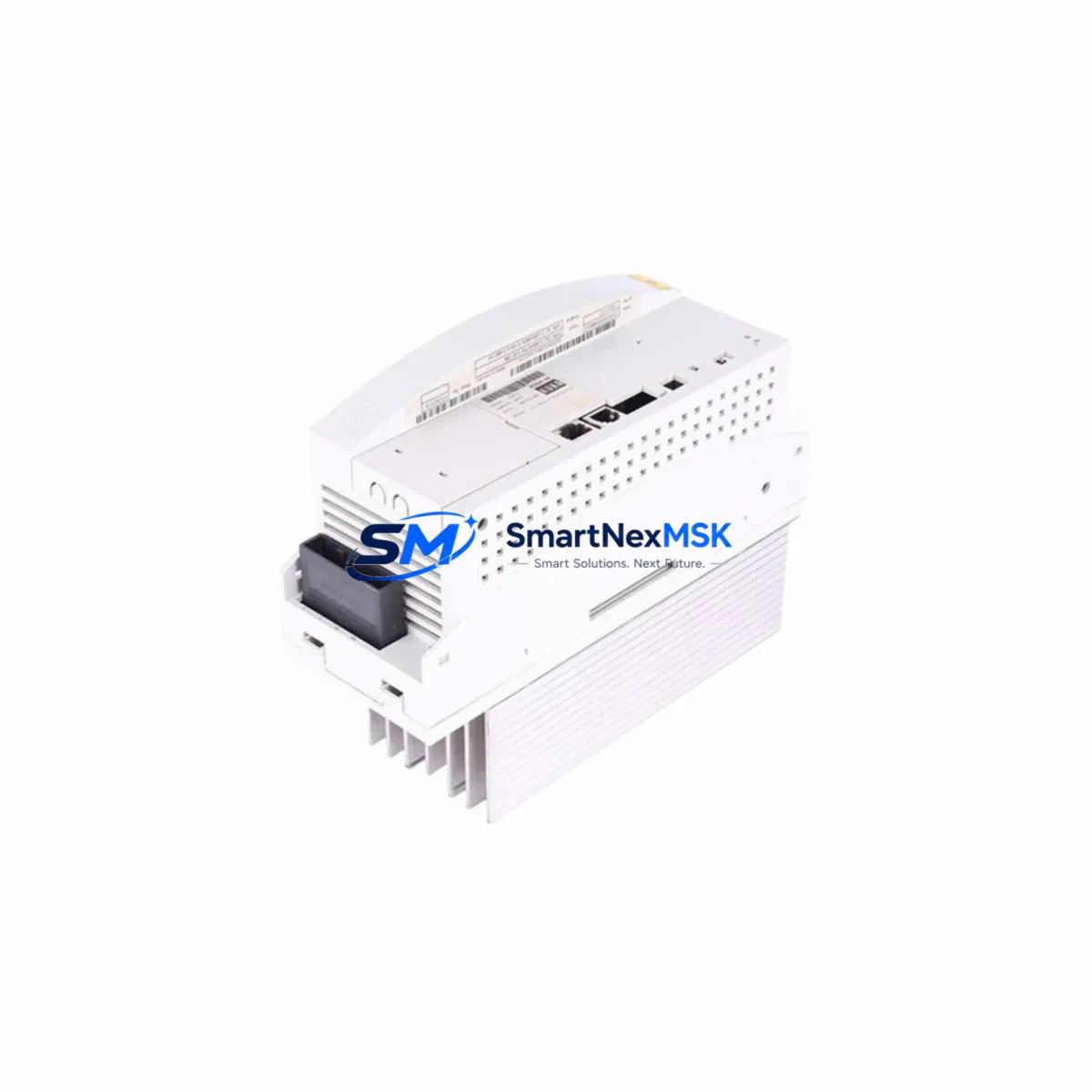
The KUKA C26D00-100-782KCP2 / 1FK7101-5AY71-1SY3-Z S77 is a 4.9 kW synchronous servo motor engineered for seamless integration into KUKA KRC2 and KRC4 robot controller platforms. As aging robot cells approach end-of-life or require axis-level drive replacement, this motor provides a verified drop-in retrofit path that preserves existing wiring harnesses, encoder feedback loops, and KRL program logic without requiring full system requalification. Whether you are recovering from an unplanned axis failure, executing a planned overhaul of a multi-robot welding line, or upgrading a legacy KRC2 cell to extend its operational lifespan by five or more years, the C26D00 delivers the mechanical and electrical compatibility your engineering team needs to minimize downtime and protect capital investment.
In retrofit and modernization projects, the servo motor is rarely replaced in isolation. A complete axis restoration typically involves verifying the KUKA KPS-600 power supply module output capacity against the new motor’s rated current draw, inspecting the KSD1-16 or KSD1-48 servo drive for firmware compatibility with the 1FK7 encoder protocol, and confirming that the DSE-IBS or DSE-RDW resolver/encoder interface board correctly interprets the motor’s Sin/Cos or EnDat 2.1 feedback signal. On KRC4 platforms, the KPP 600-20 power pack and associated KSP 600-3×40 servo pack must be checked for axis assignment and current limit parameters stored in the machine.dat configuration file.
Before committing to installation, your team should audit the existing motor cable assembly (part series 00-179-xxx) for pin-out continuity and insulation resistance, particularly on installations where the original cable has been routed through a cable drag chain for more than 50,000 operating cycles. The motor connector on the C26D00 uses the standard KUKA M23 circular connector format, which is shared across the 1FK7 and 1FK6 motor families, simplifying cable reuse. However, if the legacy installation used an earlier 1FK6101 or 1FK6081 motor, a connector adapter or new cable set may be required due to differences in the power and feedback pin assignments.
Axis address configuration is handled through the robot controller’s $MAMES[], $AXIS_ACT, and $ROBCOR system variables. After physical installation, the mastering procedure must be performed using the KUKA EMT (Electronic Mastering Tool) or the optional MEMD mastering reference notch on the motor shaft. Skipping or incorrectly executing this step is the most common cause of post-retrofit positioning errors and TCP drift. For cells running KUKA.WorkVisual project management software, the axis configuration should be exported, validated against the new motor’s rated parameters, and re-deployed to the controller before resuming production.
On the HMI side, operators using KUKA smartPAD or the legacy KCP2 teach pendant will not observe any interface changes following a like-for-like motor replacement, provided the axis mastering data is correctly restored. If the retrofit is part of a broader upgrade that includes replacing the KRC2 cabinet with a KRC4 compact or KRC4 smallsize controller, the HMI migration from KCP2 to smartPAD requires a separate software commissioning step and may involve updating the KUKA System Software (KSS) from version 5.x to 8.x, which affects teach program syntax and safety configuration.
For facilities managing multi-robot cells, it is strongly recommended to maintain a spare inventory of the C26D00 motor alongside compatible KSD servo drive modules and a set of pre-terminated motor cables. This approach, combined with a documented mastering data backup stored on the controller’s CompactFlash card or USB archive, enables axis restoration within a single shift rather than waiting for emergency procurement. All units supplied by SMARTNEXMSK are tested for insulation resistance, encoder signal integrity, and no-load rotation before shipment, and are covered by a 12-month warranty from the date of delivery.
Upgrade Compatibility Table
| Parameter | C26D00-100-782KCP2 / 1FK7101-5AY71-1SY3-Z S77 |
|---|---|
| Rated Power | 4.9 kW |
| Motor Series | KUKA 1FK7 (Siemens OEM) |
| Compatible Controllers | KRC2, KRC2 ed05, KRC4, KRC4 compact, KRC4 smallsize |
| Feedback Interface | Sin/Cos encoder / EnDat 2.1 (resolver variant available) |
| Motor Connector | M23 circular (KUKA standard, shared with 1FK6/1FK7 family) |
| Mounting Interface | Flange-mount, compatible with standard KUKA axis gearbox interface |
| Drive Compatibility | KSD1-16, KSD1-48, KSP 600-3×40 |
| Mastering Method | EMT / MEMD notch mastering |
| Replacement for | 1FK6101, 1FK7101 (same flange series), C26D00 variants |
| Commissioning Tool | KUKA.WorkVisual, KSS 5.x / 8.x |
| Warranty | 12 months from delivery date |
| Pre-shipment Testing | Insulation resistance, encoder signal, no-load rotation |
Retrofit Planning for Existing Automation Systems
A successful retrofit begins well before the motor arrives on-site. Start by pulling the robot’s current mastering data from the KRC2 or KRC4 controller archive and storing it on an external USB drive or network share. Next, verify that the KPS-600 power supply in the cabinet can sustain the inrush current during axis homing — a degraded capacitor bank in aging KPS units is a common hidden failure point that only manifests under load. Inspect the KSD1-48 servo drive assigned to the affected axis for fault history using the controller’s log viewer; recurring overcurrent or encoder faults prior to motor failure often indicate a drive that should be replaced concurrently rather than after the motor swap.
Terminal wiring on the C26D00 follows the KUKA standard color-coded scheme. The power cable (U, V, W, PE) should be torqued to the manufacturer’s specification, and the feedback cable shield must be grounded at the drive end only to prevent ground loops that cause encoder noise. If the installation includes a KUKA energy supply system (EAS) or a third-party cable management arm, verify that the new motor’s cable exit direction matches the original routing to avoid mechanical stress on the connector body during axis movement.
For cells that also require I/O expansion during the retrofit window, the KUKA KIO 16/16 digital I/O module or a compatible Profibus DP or EtherNet/IP gateway module can be installed in the KRC4 cabinet’s expansion slot without interrupting the servo axis commissioning. This is also an appropriate time to update the KUKA.SafeOperation or KUKA.SafeRangeMonitoring software packages if the cell safety configuration requires recertification following the mechanical change.
Downtime Control During System Migration
The most effective strategy for minimizing production downtime during a servo motor replacement is to complete all preparatory steps — parts staging, mastering data backup, drive parameter export, and safety zone documentation — during a scheduled maintenance window before the actual motor swap begins. With the C26D00 pre-tested and ready, the physical exchange, cable reconnection, and mastering procedure can typically be completed within two to four hours by a qualified KUKA-certified technician.
To protect original program logic, never perform a cold start of the controller without first confirming that the $ROBCOR and $MAMES[] arrays have been restored from the archived mastering data. If the controller was powered down unexpectedly due to the motor failure, use the KSS service menu to restore the last valid configuration before attempting axis movement. For multi-robot cells sharing a common KUKA.RoboTeam or DeviceNet network, isolate the affected robot’s communication node before beginning the retrofit to prevent cascading fault states on adjacent controllers.
Once the motor is installed and mastered, perform a slow-speed (T1 mode, 10% override) full-range axis sweep to confirm smooth motion, absence of encoder faults, and correct torque response before returning the cell to automatic mode. Document the post-retrofit mastering values and store them alongside the motor’s serial number and installation date for future reference and warranty validation.
Retrofit Support FAQ
Q: Is the C26D00-100-782KCP2 a direct drop-in replacement for the 1FK6101 motor on my KRC2 robot?
A: The 1FK7101 and 1FK6101 share the same flange interface and rated power class, but the encoder connector pinout differs between generations. A cable adapter or new feedback cable is typically required. We recommend confirming the existing cable part number before ordering to ensure a complete retrofit kit.
Q: Does the motor ship with a pre-tested encoder signal, and how is the 12-month warranty validated?
A: Yes. Every unit undergoes insulation resistance testing, encoder signal verification, and no-load rotation testing before shipment. The 12-month warranty is activated from the delivery date and is validated by the shipment invoice and serial number. Warranty claims are processed via sales@smartnexmsk.com.
Q: What commissioning steps are mandatory after installation on a KRC4 controller?
A: After physical installation and cable connection, you must perform axis mastering using the EMT tool or MEMD notch method, restore the $MAMES[] mastering array from your backup, and execute a T1-mode axis sweep to verify encoder feedback and motion quality. A WorkVisual project re-deployment is recommended if axis parameters were modified.
Q: Can I install this motor without replacing the KSD servo drive?
A: In most cases, yes — provided the existing KSD1-16 or KSD1-48 drive shows no fault history related to overcurrent or encoder errors. If the drive has logged repeated faults prior to motor failure, concurrent drive replacement is strongly advised to avoid a repeat failure and additional downtime.
© 2026 SMARTNEXMSK. All rights reserved.
Original Source: https://smartnexmsk.com
Contact: sales@smartnexmsk.com | +86 18259474341