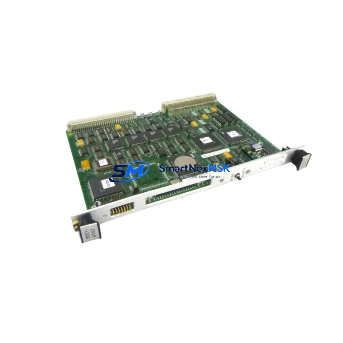
Kulicke Soffa 08001-4260 Maintenance-Ready Spare for Wire Bonder Automation
The Kulicke & Soffa 08001-4260 is a PowerPC-based CPU control board engineered for precision motion control in semiconductor wire bonding systems. As a critical processing unit within the wire bonder’s control architecture, this board governs real-time axis coordination, bonding force feedback, vision alignment sequencing, and inter-module communication. When this component fails or degrades, the entire bonding line halts — making rapid, verified spare availability the single most important factor in minimizing unplanned downtime.
For maintenance engineers managing aging wire bonder fleets, the 08001-4260 represents a high-priority line item on any preventive maintenance BOM. Its PowerPC architecture interfaces directly with the machine’s motion controller backplane, I/O expansion modules, and operator HMI panel. A board failure typically manifests as a system boot fault, axis initialization error, or intermittent communication loss between the CPU and downstream servo drives. Identifying and replacing this board quickly — with a pre-tested, original-specification unit — is the fastest path to restoring production throughput.
This listing supplies the 08001-4260 as an original-grade industrial spare: sourced from verified supply channels, functionally tested prior to shipment, and backed by a 12-month warranty covering manufacturing defects and operational failure under normal use conditions.
Spare Maintenance Table
| Part Number | 08001-4260 |
| Manufacturer | Kulicke & Soffa |
| Component Type | PowerPC CPU Control Board |
| Application | Wire Bonder Motion Control & System Processing |
| Architecture | PowerPC RISC Processor Platform |
| Interface | Backplane Bus, Serial Communication, I/O Expansion |
| Compatible Systems | Kulicke & Soffa Wire Bonder Series (PowerPC-based platforms) |
| Origin | United States |
| Weight | 2.6 kg |
| Pre-Shipment Testing | Functional power-on and communication verification |
| Warranty | 12 Months — covers manufacturing defects and operational failure |
| Lead Time | In-stock units ship within 3–5 business days |
| Packaging | Anti-static ESD bag, foam-padded export carton |
| Condition | Original spare-grade; tested before shipment |
Maintenance Planning for Continuous Operation
Replacing the 08001-4260 CPU board is rarely an isolated event. In a wire bonder control cabinet, the CPU board sits at the center of a tightly coupled electrical system. A thorough maintenance engineer will treat a CPU board replacement as an opportunity to audit the entire control enclosure. Before returning the machine to production, the following associated components should be inspected or replaced as part of the same maintenance window:
The 24VDC power supply module feeding the CPU backplane should be load-tested — an aging power supply with marginal output voltage is a common root cause of CPU board degradation and premature failure. Similarly, the backplane connector and card-edge contacts should be cleaned and inspected for oxidation or mechanical wear, as poor backplane contact causes intermittent faults that are difficult to diagnose after the fact.
The I/O expansion modules connected to the CPU bus — including digital input cards, digital output cards, and analog signal conditioning boards — should be reseated and verified for correct address mapping after any CPU replacement. Communication between the CPU and the servo drive amplifier modules controlling the X/Y/Z bonding axes must be re-validated through a full axis homing and calibration sequence.
The operator HMI panel (typically a touchscreen or keypad-based interface) communicates with the CPU via a serial or Ethernet link; this connection should be tested end-to-end after board swap. If the system uses a vision alignment controller or dedicated image processing board, its handshake with the new CPU board must be confirmed before running production wafers.
Additional components to inspect during the same maintenance event include: terminal block assemblies on the I/O wiring harness (check for loose terminations and insulation degradation), signal isolation modules on analog sensor inputs (thermocouple, force sensor, and position feedback lines), fuse holders and circuit protection devices on the 24VDC and 5VDC logic rails, and any communication interface cards (RS-232, RS-485, or Ethernet) used for host computer or MES integration. A complete inspection of these components during a planned CPU board replacement significantly reduces the probability of a secondary failure within the next maintenance cycle.
Site Replacement Workflow
The 08001-4260 is designed as a direct board-level replacement for the existing CPU assembly in compatible Kulicke & Soffa wire bonder platforms. The replacement workflow follows standard industrial PCB swap procedures:
Step 1 — Safe Isolation: Power down the wire bonder through the standard E-stop and main disconnect sequence. Verify zero-energy state on all control cabinet rails using a calibrated multimeter before opening the enclosure.
Step 2 — ESD Precautions: Ground yourself with a wrist strap before handling the CPU board. The 08001-4260 contains sensitive CMOS logic components that are susceptible to electrostatic discharge damage.
Step 3 — Board Extraction: Document the existing board’s connector positions and cable routing with photographs before disconnection. Remove all ribbon cables, backplane connectors, and any retention hardware. Extract the board carefully from the card slot.
Step 4 — Inspection & Installation: Inspect the replacement 08001-4260 for shipping damage. Verify the board revision matches or supersedes the removed unit. Install the new board, reconnect all cables in documented order, and secure retention hardware.
Step 5 — Power-On Verification: Restore power and observe the boot sequence. Confirm that the CPU initializes without fault codes, that all I/O modules are recognized, and that the HMI panel establishes communication. Run a full axis homing sequence before resuming production.
This workflow minimizes system downtime to a single maintenance shift in most cases, allowing production to resume within hours rather than days — a critical advantage when managing semiconductor packaging line throughput.
Spare Parts Support FAQ
Q: Is the 08001-4260 compatible with all Kulicke & Soffa wire bonder models?
A: The 08001-4260 is compatible with Kulicke & Soffa wire bonder platforms that use the PowerPC-based CPU control architecture. Compatibility should be confirmed against your machine’s serial number and control system revision before ordering. Contact our technical team with your machine model and software version for a pre-order compatibility check.
Q: What does the 12-month warranty cover?
A: The 12-month warranty covers manufacturing defects and operational failure under normal industrial operating conditions from the date of shipment. It does not cover damage resulting from incorrect installation, electrostatic discharge, overvoltage events, or physical mishandling. Warranty claims are processed with return shipment and replacement dispatch within 10 business days.
Q: How is the board tested before shipment?
A: Each 08001-4260 unit undergoes a functional power-on test and communication interface verification prior to packaging. Units that fail any test parameter are quarantined and not shipped. Test records are retained and available upon request for quality-critical procurement processes.
Q: What is the recommended spare inventory strategy for this board?
A: For facilities operating multiple wire bonder lines, maintaining one 08001-4260 per 3–5 machines as a cold-standby spare is a widely adopted strategy in semiconductor packaging maintenance programs. Given the lead time sensitivity of CPU-level failures and the production impact of an unplanned bonding line stoppage, holding a pre-tested spare on-site eliminates the most critical gap in your downtime recovery plan.
© 2026 SMARTNEXMSK. All rights reserved.
Original Source: https://smartnexmsk.com
Contact: sales@smartnexmsk.com | +86 18259474341