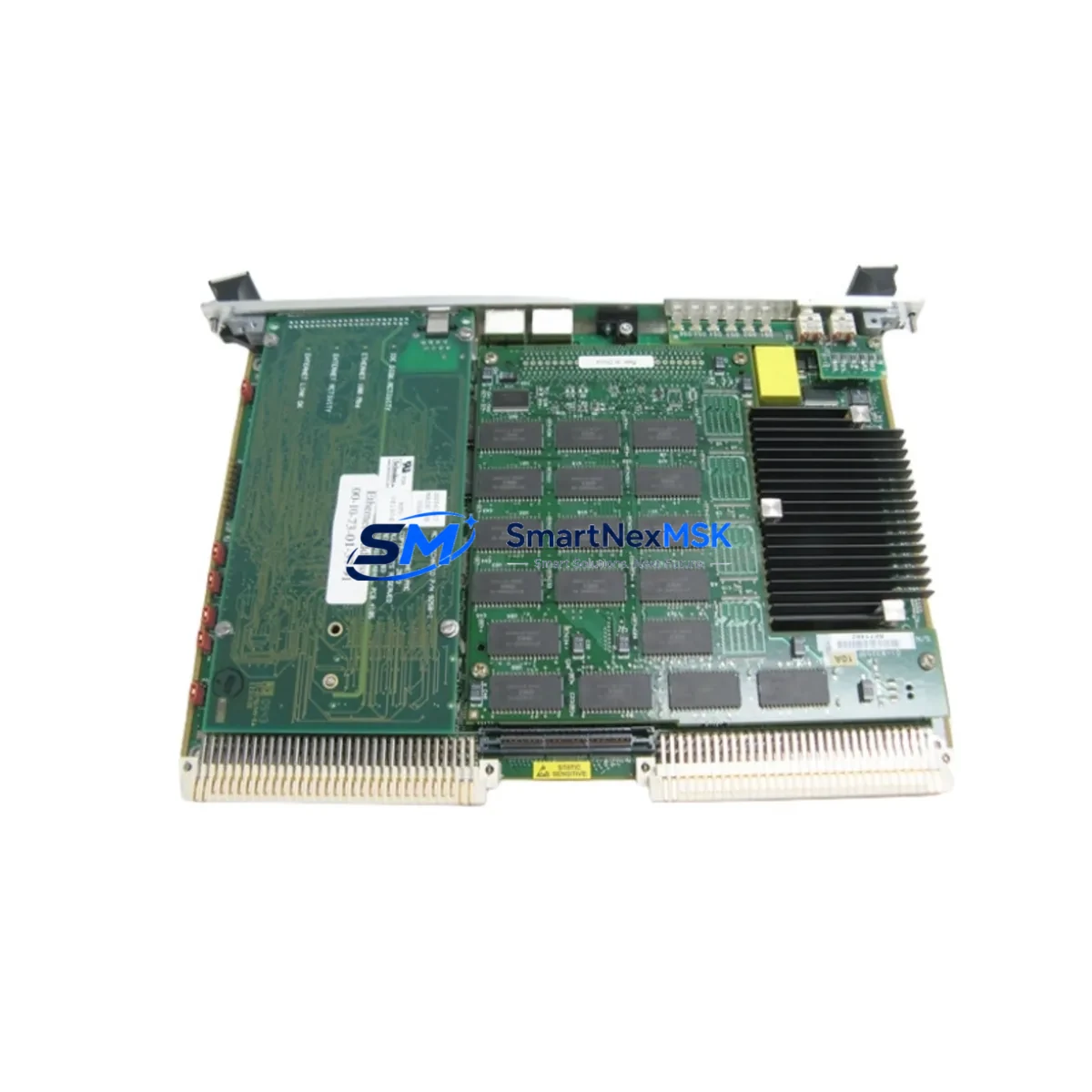
KULICKE & SOFFA 8002-4192 Retrofit-Ready I/O Temperature Board for Wire Bonder Control Systems
The KULICKE & SOFFA 8002-4192 I/O Temperature Board is a precision-engineered replacement and retrofit solution designed for Wire Bonder Series control systems. As semiconductor packaging equipment ages and OEM support windows close, facilities managing legacy wire bonding lines face increasing pressure to source verified replacement boards that maintain process continuity without requiring full machine replacement. The 8002-4192 addresses this challenge directly — offering a drop-in compatible I/O temperature interface board that restores full thermal monitoring and control functionality to existing Wire Bonder platforms.
This board manages the critical temperature I/O signals that govern bonding head thermal regulation, transducer heating circuits, and substrate temperature feedback loops within the Wire Bonder control architecture. Incorrect temperature readings or signal dropouts in these circuits directly impact bond quality, wire pull strength, and yield rates. Sourcing a verified, tested replacement is therefore not a routine spare parts decision — it is a process-critical engineering action.
Upgrade Compatibility Table
| Parameter | Details |
|---|---|
| Part Number | 8002-4192 |
| Brand | KULICKE & SOFFA |
| Function | I/O Temperature Board — thermal signal acquisition and control interface |
| Compatible Platform | KULICKE & SOFFA Wire Bonder Series (8000-series control architecture) |
| Interface / Backplane | Internal card-edge connector; compatible with 8000-series backplane slot assignments |
| Installation Requirement | Direct board swap; verify slot address and jumper configuration before installation |
| Communication Compatibility | Parallel I/O bus; no protocol migration required for same-series replacement |
| Replacement Recommendation | Verified drop-in replacement for failed or degraded OEM 8002-4192 boards |
| Commissioning Focus | Thermocouple channel calibration, offset verification, alarm threshold confirmation |
| Warranty | 12-Month Warranty — covers functional defects under normal operating conditions |
Retrofit Planning for Existing Automation Systems
Replacing the 8002-4192 in an operational Wire Bonder line requires a structured retrofit approach that accounts for the interdependencies between the temperature board and the broader machine control architecture. Before initiating the swap, engineers should document the current thermocouple wiring assignments at the terminal block, noting which channels correspond to bond head, substrate chuck, and transducer heating zones. The 8002-4192 interfaces with the machine’s main CPU board — typically a companion card within the same 8000-series card cage — and any mismatch in channel mapping will produce erroneous temperature readings that may not immediately trigger alarms but will degrade bond quality over time.
The card cage backplane in Wire Bonder systems of this generation uses a passive bus architecture. When removing the failed board, inspect the backplane connector pins for oxidation or mechanical damage before seating the replacement. If the system also uses a separate power supply board within the same cage, verify that the supply rails — typically +5 VDC and ±12 VDC — are within specification before powering up with the new board installed. A degraded power supply board is a common secondary failure mode that can damage replacement I/O boards if not addressed first.
For facilities running multiple Wire Bonder units, it is advisable to maintain a small buffer stock of critical interface boards including the 8002-4192, along with companion components such as the machine’s servo driver boards, encoder interface cards, and motion controller modules. These components share similar aging profiles and are frequently unavailable through OEM channels once a machine series reaches end-of-life status. Proactive stocking of the bond force sensor interface board, the ultrasonic generator control board, and the vision system interface card significantly reduces unplanned downtime risk across the bonding line.
When the Wire Bonder system also includes an HMI terminal for process parameter entry and alarm display, confirm that the HMI screen assignments for temperature channels remain consistent after the board replacement. Some configurations store channel-to-display mappings in the HMI controller rather than in the I/O board itself, meaning the display will continue to function correctly. However, if the system uses a programmable logic controller as an intermediary — for example, a rack-mounted PLC handling supervisory temperature alarming — verify that the PLC’s analog input module address assignments and scaling parameters are unchanged. Any reconfiguration of the PLC program should be performed with a backup of the original ladder logic retained on the programming terminal.
For Wire Bonder lines integrated into broader semiconductor assembly automation, the 8002-4192 replacement may also require coordination with upstream and downstream equipment controllers. Die attach systems, plasma cleaners, and encapsulation dispensers that share a common factory automation network should be placed in a safe hold state during the board swap to prevent process sequencing errors triggered by temporary temperature signal loss.
Downtime Control During System Migration
Minimizing downtime during a Wire Bonder I/O temperature board replacement begins with preparation completed before the machine is taken offline. A complete pre-swap checklist should include: photographing all thermocouple and signal wiring at the terminal strip, recording current temperature setpoints and alarm thresholds from the HMI or operator panel, and saving a backup of any PLC or machine controller program that references temperature I/O addresses.
The physical board swap on a card-cage architecture like the 8000-series Wire Bonder is typically a 15–30 minute mechanical operation when the replacement board is on hand and the wiring documentation is complete. The majority of downtime in unplanned replacement scenarios comes from sourcing delays, not from the installation itself. Maintaining a verified spare of the 8002-4192 on-site eliminates this sourcing delay entirely.
After installation, the commissioning sequence should begin with a cold power-up check — verifying supply voltages at the backplane before enabling the machine’s main control power. Once the system initializes, compare live temperature readings on all channels against a calibrated reference thermometer at ambient temperature to confirm channel accuracy before resuming production. If the system uses a separate calibration routine accessible through the machine’s service menu, execute this routine and record the results as part of the maintenance log. This documented commissioning process also supports the 12-month warranty claim process should any functional issue arise after installation.
For facilities with strict OEE targets, scheduling the board replacement during a planned preventive maintenance window — rather than responding reactively to a failure — is strongly recommended. A proactive replacement of a board showing early signs of thermal drift or intermittent channel faults will cost a fraction of the downtime associated with an unplanned failure during a production run.
Retrofit Support FAQ
Q1: Is the 8002-4192 a direct drop-in replacement for the original OEM board?
Yes. The 8002-4192 supplied by SMARTNEXMSK is a verified functional replacement for the original KULICKE & SOFFA 8002-4192 I/O Temperature Board. It is compatible with the 8000-series Wire Bonder card cage backplane and terminal wiring. No firmware modification or hardware adaptation is required for a same-series replacement. Each unit undergoes functional testing prior to shipment.
Q2: What wiring checks should be performed before installing the replacement board?
Before installation, document all thermocouple connections at the terminal strip, noting wire color coding and channel assignments. Verify that thermocouple types (typically Type K or Type J in Wire Bonder applications) match the board’s input configuration. Check terminal screw torque and inspect for any signs of heat damage or oxidation at the connector interface. Confirm that the backplane slot designated for the 8002-4192 is free of debris and that the connector pins are undamaged.
Q3: Can this board be used in Wire Bonder units from different production years within the 8000 series?
The 8002-4192 is designed for the KULICKE & SOFFA 8000-series Wire Bonder platform. Compatibility across specific production years within this series depends on the machine’s hardware revision level and backplane configuration. If you are uncertain about compatibility for your specific machine serial number, contact SMARTNEXMSK with your machine model and serial number for a pre-sale compatibility confirmation before ordering.
Q4: What does the 12-month warranty cover, and how is a warranty claim initiated?
The 12-month warranty covers functional defects in the 8002-4192 board under normal operating conditions, including failures attributable to component defects or manufacturing quality. It does not cover damage resulting from incorrect installation, overvoltage conditions, or physical mishandling. To initiate a warranty claim, contact SMARTNEXMSK with your order reference, a description of the observed fault, and the commissioning test results recorded at installation. Replacement or repair will be arranged promptly upon fault verification.
© 2026 SMARTNEXMSK. All rights reserved.
Original Source: https://smartnexmsk.com
Contact: sales@smartnexmsk.com | +86 18259474341