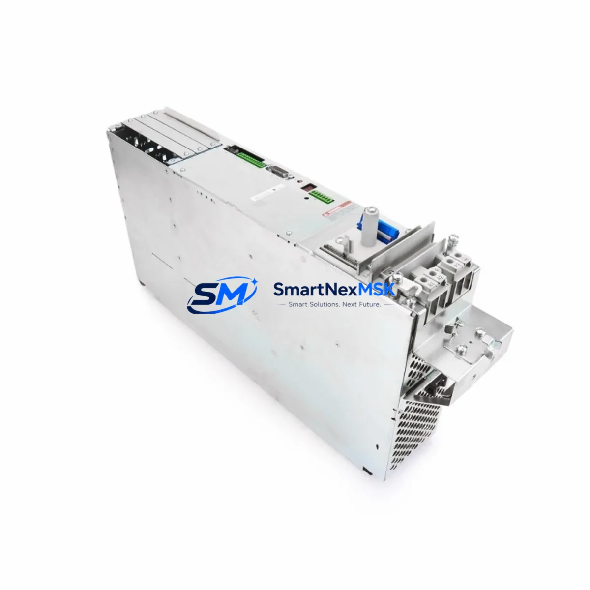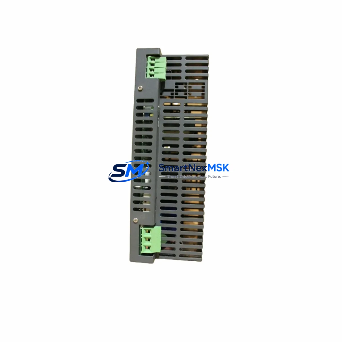
LinMot S01-72/600 Retrofit-Ready Power Supply for S01 Series: Seamless Compatibility and Legacy System Upgrade
The LinMot S01-72/600 is a 72 VDC, 600 W dedicated power supply unit engineered for LinMot S01 Series linear motor drive systems. As industrial facilities face increasing pressure to modernize aging automation infrastructure, the S01-72/600 serves as a critical retrofit component — enabling engineers to replace end-of-life PSUs, restore discontinued control cabinet assemblies, and extend the operational life of existing LinMot linear motor platforms without requiring a full system redesign.
Whether you are upgrading a legacy production line, recovering from an unplanned PSU failure, or migrating from an older LinMot drive generation, the S01-72/600 provides a verified drop-in replacement path that preserves your existing wiring topology, terminal assignments, and motor control logic.
Upgrade Compatibility Table
| Parameter | S01-72/600 Specification | Retrofit Notes |
|---|---|---|
| Output Voltage | 72 VDC | Verify bus voltage matches existing LinMot drive input rating |
| Output Power | 600 W continuous | Confirm total motor load does not exceed PSU capacity |
| Input Voltage | 3 × 400 VAC / 50–60 Hz | Check cabinet incoming supply; single-phase variants require transformer |
| Mounting | DIN rail / panel mount | Compatible with standard LinMot S01 Series backplane and control cabinet layouts |
| Communication | DC bus interface to LinMot C-Series drives | No protocol change required; bus topology preserved |
| Replacement Fit | Direct drop-in for S01-72/600 OEM units | Terminal block pinout identical; no rewiring needed |
| Commissioning | LinMot Talk software compatible | Existing parameter files and motion profiles remain valid |
| Warranty | 12 Months | Covers manufacturing defects; pre-shipment functional test included |
Retrofit Planning for Existing Automation Systems
Successful integration of the S01-72/600 into a legacy control system begins with a structured pre-retrofit audit. Engineers should document the existing cabinet layout, including the positions of the LinMot C1100 series servo drive, the LinMot E1200 series linear motor, and any associated LinMot P01-48×240 or P01-70×240 linear motors connected to the DC bus. Confirm that the 72 VDC bus rail capacity is sufficient for the combined peak current demand of all connected axes.
Terminal block wiring should be verified against the original S01-72/600 wiring diagram. The L+, L−, PE, and AC input terminals follow a standardized layout across the S01 Series, meaning that replacement units can be installed without modifying existing cable harnesses. If the cabinet also houses a LinMot E1100 drive module or a LinMot C1250 controller, confirm that the shared DC bus voltage tolerance is within specification before energizing the replacement PSU.
For systems that include LinMot B1100 brake modules or regenerative braking resistors, verify that the braking circuit interface remains compatible with the replacement unit’s internal bus capacitance and regeneration handling. In multi-axis configurations where the S01-72/600 feeds both a primary and secondary drive channel, load balancing across the bus should be recalculated if any motor or drive has been upgraded since the original installation.
If the retrofit also involves migrating from an older LinMot Talk 4.x parameter set to a newer firmware version, back up all existing motion profiles, cam tables, and I/O assignments before replacing the PSU. The S01-72/600 does not store application parameters, but a firmware mismatch between the drive and the new PSU’s internal firmware can affect bus initialization sequences. Pre-test the replacement unit on a bench setup using a LinMot programming cable (IF-E1/USB) before installing it in the live cabinet.
Downtime Control During System Migration
Minimizing unplanned downtime during a PSU replacement requires a structured swap procedure. Begin by placing the affected axis in a safe, parked position and disabling the drive enable signal from the PLC — typically a Siemens S7-300, Allen-Bradley CompactLogix, or Beckhoff CX series controller — before de-energizing the cabinet. Label all terminal connections on the outgoing S01-72/600 with numbered tags before disconnection to eliminate rewiring errors during installation of the replacement unit.
After mechanical installation, perform a cold-start sequence: apply AC input power first, confirm the 72 VDC bus rail reaches nominal voltage within the specified rise time, then re-enable the drive. Use LinMot Talk to verify that the drive recognizes the PSU and that all axis parameters are intact. If the system uses an HMI panel — such as a Siemens TP700 or a Weintek MT8000 series — confirm that the motor status screens reflect correct drive state before resuming automatic operation. The entire hot-swap procedure, when pre-planned, can typically be completed within 30–60 minutes, preserving production continuity and avoiding extended line stoppages.
Retrofit Support FAQ
Q1: Is the S01-72/600 a direct replacement for the original LinMot OEM unit?
Yes. The S01-72/600 is a form-fit-function replacement for the original LinMot S01-72/600 OEM power supply. Terminal pinout, mounting dimensions, and DC bus output specifications are identical. No rewiring or mechanical modification is required for a standard cabinet installation.
Q2: What commissioning steps are required after installation?
After installing the replacement unit, power up the cabinet and use LinMot Talk software to verify bus voltage, drive communication status, and axis parameter integrity. If the drive firmware has been updated since the original installation, re-upload the saved parameter file to ensure motion profile compatibility. No re-teaching of motor positions is required if the mechanical system has not been disturbed.
Q3: Can the S01-72/600 support multi-axis configurations?
Yes, provided the total continuous and peak power demand of all connected axes does not exceed the 600 W rated output. For higher-load multi-axis systems, consider paralleling with an additional S01-72/600 unit or upgrading to a higher-capacity LinMot PSU variant. Consult the LinMot system design guide for bus loading calculations.
Q4: What does the 12-month warranty cover?
The 12-month warranty covers manufacturing defects and component failures under normal operating conditions. Each unit undergoes a pre-shipment functional test including output voltage verification, load regulation check, and thermal cycling. Warranty claims are processed via our sales team with a standard RMA procedure. Physical damage, incorrect wiring, or operation outside rated input voltage range are excluded from warranty coverage.
© 2026 SMARTNEXMSK. All rights reserved.
Original Source: https://smartnexmsk.com
Contact: sales@smartnexmsk.com | +86 18259474341