Metso PDP401 Retrofit-Ready DCS Processor for DNA Series: Compatible Modernization & Legacy System Smooth Upgrade
The Metso PDP401 is a distributed processing unit (DPU) engineered for the Metso DNA Distributed Control System platform — one of the most widely deployed DCS architectures across pulp and paper, power generation, chemical processing, and water treatment industries worldwide. As original PDP401 units approach end-of-life and OEM spare parts become increasingly scarce, plant engineers and maintenance teams are actively seeking verified retrofit-ready replacements that preserve existing backplane wiring, terminal connections, and application program logic without requiring a full system overhaul or costly platform migration.
This listing provides a tested, in-stock PDP401 module sourced from authorized supply channels, backed by a 12-month warranty and pre-shipment functional verification. Whether you are replacing a failed unit on an active production line, building a critical spare inventory for aging DNA Series control stations, or executing a phased control system modernization, the PDP401 delivers a direct drop-in solution for DNA Series control cabinets with minimal commissioning time and maximum compatibility assurance.
Upgrade Compatibility Table
| Parameter | Detail |
|---|---|
| Compatible Platform | Metso DNA DCS (Distributed Control System) |
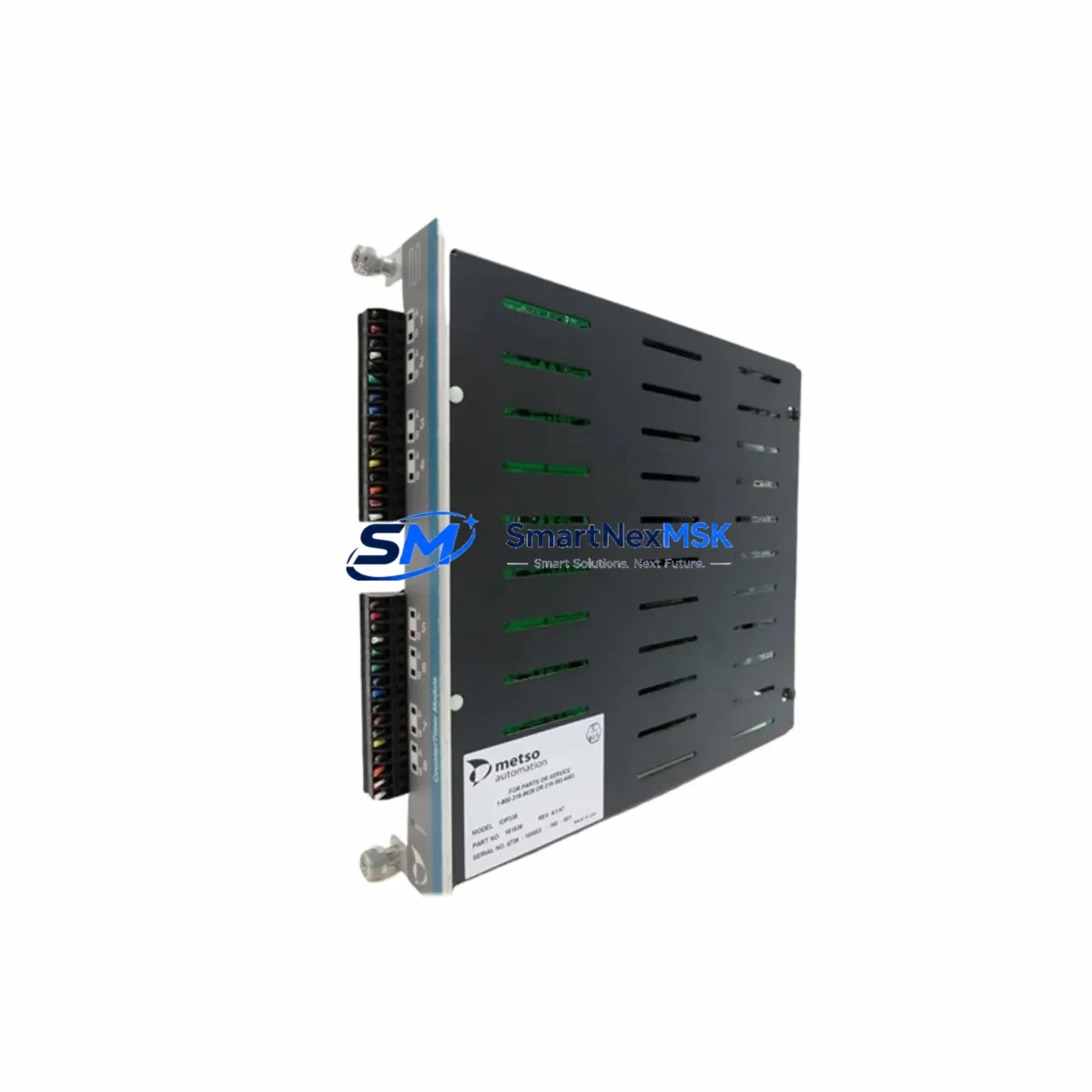
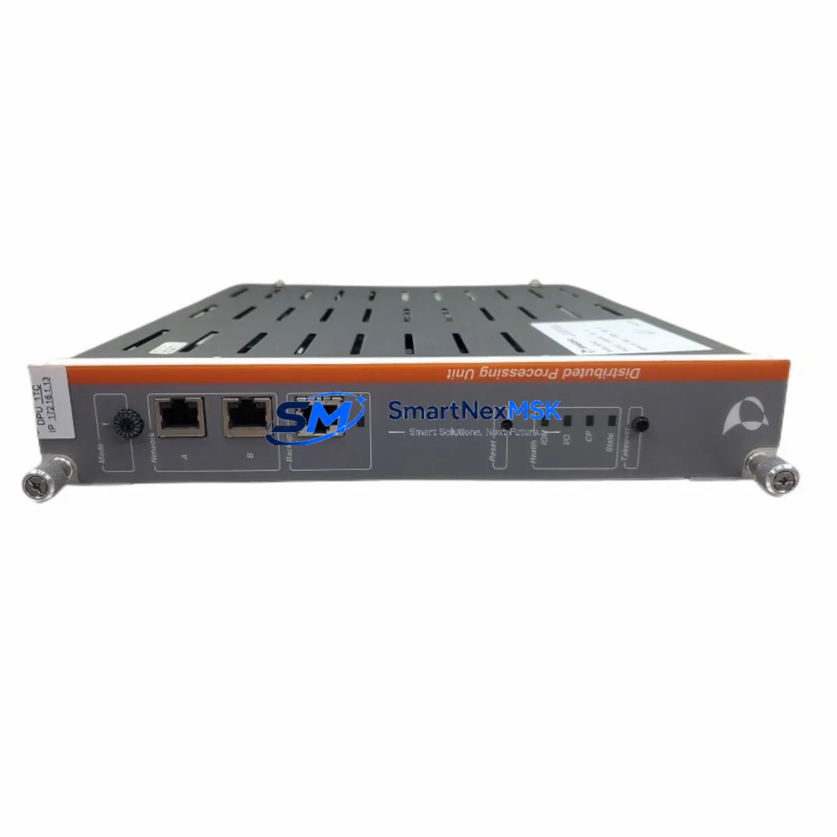
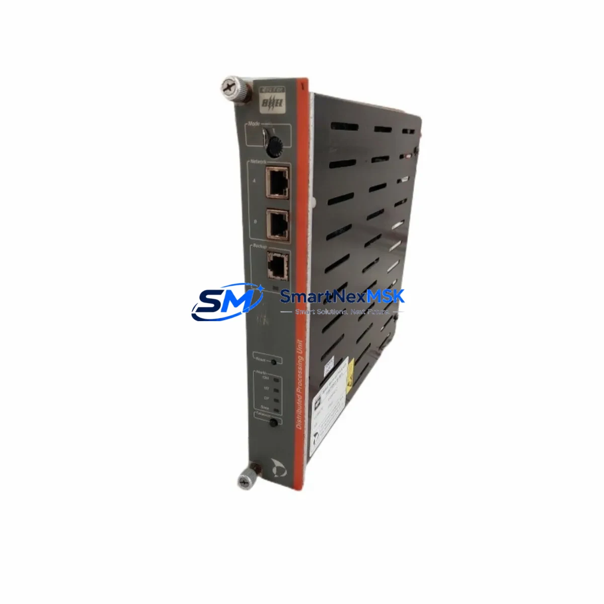
| Module Type | Distributed Processing Unit (DPU) |
| Backplane Interface | DNA Series standard backplane bus — direct slot replacement, no adapter required |
| Communication Protocol | Metso DNA proprietary fieldbus; gateway-compatible with PROFIBUS DP and Modbus RTU |
| I/O Compatibility | Compatible with DNA Series I/O modules: AI401, DI401, AO401, DO401 terminal blocks |
| Power Supply Requirement | 24 VDC via backplane; verify PSU401 capacity before hot-swap or cold replacement |
| Installation Method | DIN rail / rack-mount per DNA Series cabinet standard; keyed backplane connector |
| Replacement Recommendation | Direct 1:1 replacement for failed, obsolete, or end-of-life PDP401 units |
| Commissioning Note | Module address must be re-confirmed in DNA Engineering Tool after swap; OPC tag feeds require reconnection sequence |
| 12-Month Warranty | Covers manufacturing defects from date of shipment; return-and-replace logistics included at no additional cost |
Retrofit Planning for Existing Automation Systems
A successful PDP401 retrofit begins well before the replacement module arrives on-site. Engineers should start by auditing the existing DNA Series control cabinet layout, confirming the rack slot assignment, backplane bus segment, and module address of the failed or aging unit. The PDP401 occupies a standard DNA backplane slot, so physical installation is straightforward — but the surrounding ecosystem of I/O modules, power supplies, and communication links requires careful pre-planning to avoid secondary faults during the changeover.
Power supply capacity is the first checkpoint. The DNA Series PSU401 or equivalent 24 VDC rail-mount power supply modules must have sufficient headroom to support the replacement PDP401 without triggering undervoltage faults on adjacent I/O modules. Review the cabinet load calculation and confirm that the PSU401 output current rating covers the combined draw of the PDP401 and all connected AI401, DI401, AO401, and DO401 terminal modules before proceeding with the swap.
Terminal wiring for field I/O connections is typically preserved during a PDP401 swap, as the module interfaces with the DNA backplane rather than directly with field terminals. However, if the retrofit involves migrating from an older DNA generation to a current-generation DPU, verify that the AI401 analog input modules and DI401 digital input modules remain pin-compatible with the new processor’s I/O addressing scheme. In cases where the original wiring used non-standard terminal assignments, a wiring compatibility checklist should be prepared before the maintenance window begins.
Communication link integrity is critical for systems where the PDP401 acts as a local controller node. If the control cabinet includes a CM401 communication module or a PROFIBUS DP gateway connecting to field instruments, confirm that the new PDP401 is recognized on the fieldbus segment after installation. In architectures where the PDP401 communicates upstream to a DNA AC800M supervisory controller or an equivalent OPC server node, the node address and network topology must be validated in the DNA Engineering Tool before returning any control loop to automatic mode.
For plants running legacy HMI screens built on Metso DNA Operate or third-party SCADA platforms connected via OPC DA or OPC UA, the tag database and server configuration should be reviewed prior to the swap. A PDP401 replacement does not alter tag names or addresses, but a cold-start of the module may temporarily interrupt OPC data feeds — plan for a brief HMI reconnection sequence and notify operators of the expected data gap during commissioning. Where the retrofit scope extends beyond a single module — for example, when upgrading an entire control station that includes the PDP401, associated I/O racks, a local FBM401 fieldbus module, and a DP401 digital output module — consider staging the work across multiple maintenance windows to minimize exposure and preserve process control continuity at each step.
Programming cable access is another practical consideration. If the DNA Engineering Tool connection to the PDP401 is routed through a dedicated programming cable or a local Ethernet port on the module front panel, confirm that the cable and laptop configuration are prepared before the maintenance window. Having the replacement module pre-loaded with the correct application program offline eliminates on-site download time and reduces the live outage to the physical swap and loop checkout sequence only.
Downtime Control During System Migration
Minimizing unplanned downtime is the primary concern for any PDP401 replacement on a live production system. The recommended approach is to pre-configure the replacement module offline using the DNA Engineering Tool, loading the existing application program, verifying I/O mapping, and confirming module address assignments before the scheduled maintenance window begins. This preparation eliminates on-site programming time and reduces the live outage to the physical swap and loop checkout sequence — typically under two hours for a single PDP401 station replacement.
Before powering down the affected control station, export and archive the current PDP401 application program, module configuration file, and diagnostic logs from the DNA Engineering Tool. This backup serves as the recovery baseline if the new module requires re-commissioning or if an unexpected configuration mismatch is discovered during startup. Confirm that the DNA system’s redundancy architecture — if present, using a redundant DPU pair — has successfully transferred control to the standby path before isolating the primary PDP401 for removal.
During the physical swap, follow the DNA Series module extraction procedure: release the front-panel locking lever, slide the module from the backplane slot, and insert the replacement PDP401 into the same position. The backplane connector is keyed to prevent misalignment. After seating the module and securing the locking lever, restore power and monitor the DNA system status display for initialization confirmation — the module LED indicators should transition from fault to run state within the normal boot sequence timeframe before re-enabling field I/O.
Post-swap loop checkout should cover all I/O points associated with the PDP401 station: analog input scaling verification against field transmitter signals, digital output functional tests with field device confirmation, and communication link status confirmation on the CM401 or PROFIBUS DP segment. Document the commissioning results, update the plant’s maintenance records, and confirm with the control room operator that all HMI displays are returning live data before closing the maintenance work order. Proper pre-staging and a disciplined checkout sequence consistently deliver total planned downtime under two hours for a single PDP401 replacement, with zero impact on adjacent control stations.
Retrofit Support FAQ
Q1: Is the PDP401 a direct replacement for all DNA Series distributed processing units, or only specific generations?
The PDP401 is designed for the Metso DNA DCS platform and is compatible with standard DNA Series backplane slots. Compatibility with specific DNA generations should be confirmed against your system’s hardware revision documentation. Contact our technical team with your existing module’s firmware version and DNA system release number for a definitive compatibility assessment before ordering.
Q2: What wiring changes are required when replacing a failed PDP401?
In most cases, no field wiring changes are required. The PDP401 interfaces with the DNA backplane, and field terminals connect to separate I/O modules — AI401, DI401, AO401, DO401 — that remain in place during the swap. If your retrofit involves upgrading to a different I/O architecture or migrating terminal blocks to a new generation, our team can provide a wiring compatibility checklist on request prior to shipment.
Q3: How is the replacement PDP401 tested before shipment?
Every PDP401 unit undergoes pre-shipment functional verification including power-on self-test, backplane communication check, and I/O channel continuity testing. Units are shipped with a test report confirming pass status. The 12-month warranty covers manufacturing defects and includes return-and-replace logistics at no additional cost from the date of shipment.
Q4: Can the PDP401 be used in a system that has already partially migrated to a newer DCS platform?
Yes. The PDP401 is commonly deployed in hybrid migration scenarios where legacy DNA stations coexist with newer control infrastructure or a parallel AC800M supervisory layer. In these configurations, the PDP401 continues to manage its assigned I/O and communicates upstream via the existing DNA network segment. Coordination with the system integrator is recommended to ensure that the module address and network segment assignments do not conflict with the new platform’s addressing scheme during the transition period.
© 2026 SMARTNEXMSK. All rights reserved.
Original Source: https://smartnexmsk.com
Contact: sales@smartnexmsk.com | +86 18259474341