Motorola MVME133A-20: Retrofit-Ready VMEbus SBC for MVME100 Series Control Systems
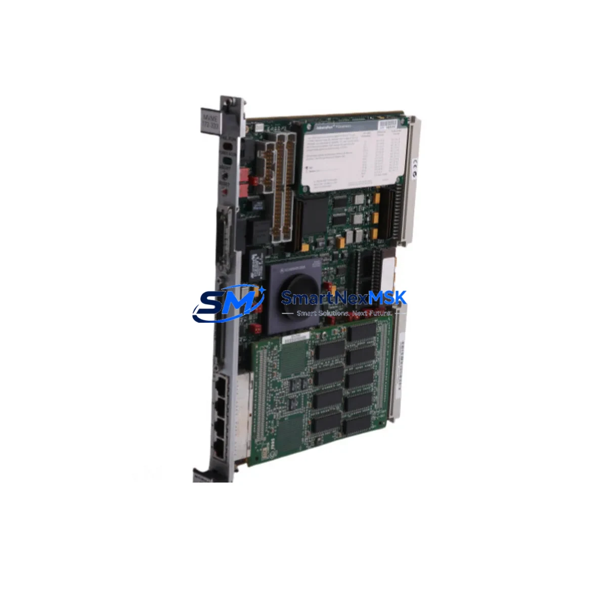
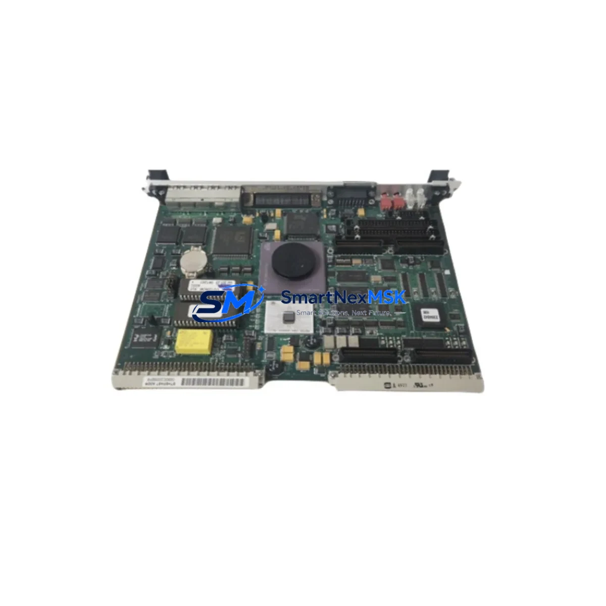
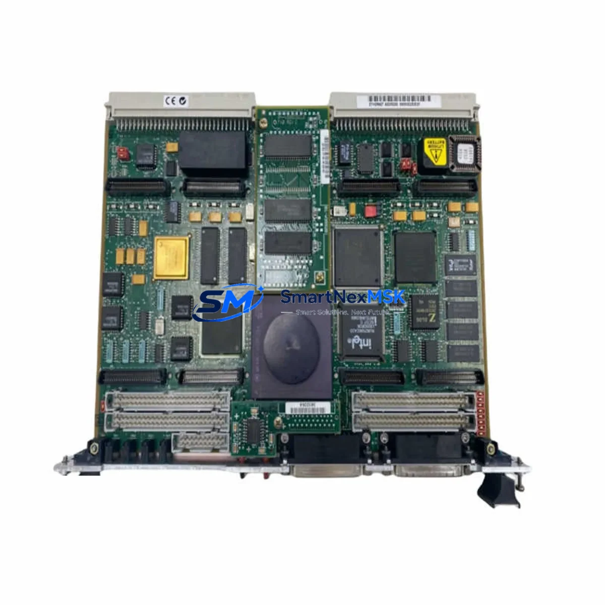
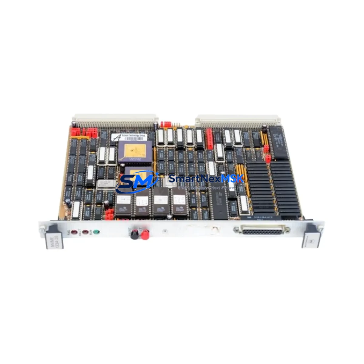
The Motorola MVME133A-20 is a high-performance VMEbus Single-Board Computer built around the Motorola MC68030 processor running at 20 MHz. Designed as a direct retrofit replacement for legacy MVME100 Series boards, this module enables industrial facilities to modernize aging control architectures without full system redesign. Whether you are replacing a failed board in a running production line, upgrading a discontinued spare, or migrating a VMEbus control cabinet to a more supportable platform, the MVME133A-20 delivers the compatibility, reliability, and supply assurance that industrial engineers demand.
At SMARTNEXMSK, every MVME133A-20 unit is sourced from verified supply channels, subjected to pre-shipment functional testing, and backed by a 12-month warranty. We maintain in-stock inventory to support urgent replacement scenarios, minimizing unplanned downtime for your facility.
Upgrade Compatibility Table
| Parameter | MVME133A-20 (Replacement) | MVME100 Series (Legacy) |
|---|---|---|
| Processor | Motorola MC68030 @ 20 MHz | MC68010 / MC68020 variants |
| Bus Interface | VMEbus (IEEE 1014) | VMEbus (IEEE 1014) |
| Form Factor | 6U VME Single-Board | 6U VME Single-Board |
| Memory | Up to 4 MB DRAM onboard | Varies by sub-model |
| Serial Ports | 2× RS-232C (P2 connector) | 2× RS-232C |
| Installation | Direct slot insertion, standard VME backplane | Standard VME backplane |
| Communication Compatibility | RS-232, VMEbus data transfer | RS-232, VMEbus |
| Replacement Recommendation | Direct drop-in for MVME100, MVME120, MVME122 variants | — |
| Commissioning Focus | IRQ level, memory map, boot ROM address, SCSI ID | — |
| Warranty | 12 Months | No longer supported |
Retrofit Planning for Existing Automation Systems
Replacing the MVME133A-20 in an operational VMEbus control cabinet requires careful pre-migration planning. Before removing the legacy board, engineers should document the existing memory map configuration, interrupt request (IRQ) assignments, and SCSI device IDs if a hard disk or tape drive is connected via the onboard NCR 53C90 SCSI controller. The MVME133A-20 uses a P1/P2 VMEbus connector arrangement standard across the MVME100 family, so physical backplane fitment is straightforward — however, jumper settings for DRAM size, ROM base address, and system controller designation must be verified against the original board’s configuration sheet before power-up.
In systems where the MVME133A-20 operates alongside an MVME712M transition module or an MVME050 VMEbus interrupter, the interrupt acknowledge cycle timing must be confirmed to remain within VMEbus specification. If the control cabinet also houses an MVME376 Ethernet controller or an MVME332XT serial I/O module, these boards communicate over the VMEbus backplane and are unaffected by the CPU board swap — provided the new MVME133A-20 is configured as system controller only if no other board holds that role.
For systems running real-time operating environments such as VxWorks or OS-9, the boot sequence stored in the onboard MVME133A-20 ROM monitor (MVME133Bug) must be validated against the application software’s expected entry points. If the legacy system used an MVME147 or MVME167 as the primary CPU and the MVME133A-20 is being introduced as a secondary processor or co-processor node, VMEbus arbitration priority settings on the MVME040 or similar arbiter module must be adjusted accordingly.
Power supply capacity is a critical checkpoint. The MVME133A-20 draws from the VMEbus +5V and ±12V rails. Before installation, verify that the existing MVME945 or equivalent VMEbus power supply can sustain the additional load, particularly in high-density chassis configurations where multiple I/O modules — such as the MVME616 SCSI/memory board or additional serial interface cards — are already installed. A power margin of at least 20% above the calculated load is recommended for long-term reliability.
Terminal wiring on the P2 connector for RS-232 serial ports should be re-verified after board swap. Pin assignments on the MVME133A-20 match the MVME100 Series standard, but cable harnesses that were field-modified on the original installation may not conform to the factory pinout. Use a breakout board or continuity tester to confirm signal integrity on TXD, RXD, RTS, CTS, and GND lines before enabling serial communication to connected HMI panels or SCADA hosts.
Downtime Control During System Migration
Minimizing production downtime during a VMEbus CPU board replacement requires a structured swap procedure. Begin by creating a full backup of the application program stored in battery-backed SRAM or on the SCSI-attached storage device. If the system uses an HMI panel — such as a legacy Motorola or third-party VMEbus-connected display — capture all screen configurations and tag mappings before the board is removed, as some HMI platforms store display logic in shared memory regions that are CPU-board-dependent.
Power down the VMEbus chassis in the correct sequence: disable field I/O first, then halt the CPU, then remove power from the backplane. This sequence protects connected field devices and prevents spurious output signals during the transition. After installing the MVME133A-20 and confirming jumper settings, perform a cold boot with no application loaded to verify that the ROM monitor initializes correctly and that all VMEbus slots are recognized. Only after successful ROM monitor operation should the application program be reloaded and field I/O re-enabled.
For systems where continuous operation is critical, consider staging the replacement during a scheduled maintenance window and pre-configuring the MVME133A-20 on a bench test fixture before bringing it to the production floor. This approach allows full verification of memory map, serial port operation, and SCSI device recognition in a controlled environment, reducing on-site commissioning time to under 30 minutes in most cases. All MVME133A-20 units shipped by SMARTNEXMSK are pre-tested under power to confirm basic functionality before dispatch, further reducing field commissioning risk.
Retrofit Support FAQ
Q1: Is the MVME133A-20 a direct replacement for all MVME100 Series boards?
The MVME133A-20 is compatible with the majority of MVME100 Series applications, including systems originally using the MVME120 and MVME122. However, sub-models with custom ROM configurations or non-standard P2 wiring may require jumper adjustment or ROM re-programming. We recommend providing your original board’s part number suffix and configuration sheet for pre-shipment verification.
Q2: What commissioning steps are required after installation?
After physical installation, set the system controller jumper, configure the DRAM size jumpers to match your application’s memory requirements, verify the ROM base address, and confirm SCSI ID settings if applicable. Boot to the MVME133Bug ROM monitor prompt and run the self-test routine before loading your application. Serial port loopback testing is also recommended to confirm P2 connector wiring integrity.
Q3: Can the MVME133A-20 operate in a mixed VMEbus chassis alongside newer modules?
Yes. The MVME133A-20 conforms to the VMEbus IEEE 1014 standard and will coexist with other compliant modules in the same chassis. Arbitration priority and interrupt level assignments must be configured to avoid conflicts with other boards. Modules such as the MVME376 Ethernet controller or MVME332XT serial I/O board are fully compatible in a shared backplane environment.
Q4: What does the 12-month warranty cover?
All MVME133A-20 units supplied by SMARTNEXMSK are covered by a 12-month warranty against manufacturing defects and functional failure under normal operating conditions. Each unit undergoes pre-shipment power-on testing. In the event of a warranty claim, we provide advance replacement to minimize your downtime. Warranty does not cover damage resulting from incorrect installation, overvoltage, or physical impact.
© 2026 SMARTNEXMSK. All rights reserved.
Original Source: https://smartnexmsk.com
Contact: sales@smartnexmsk.com | +86 18259474341