Motorola MVME172-333 Retrofit-Ready VMEbus SBC: Seamless Compatibility for Legacy System Upgrades
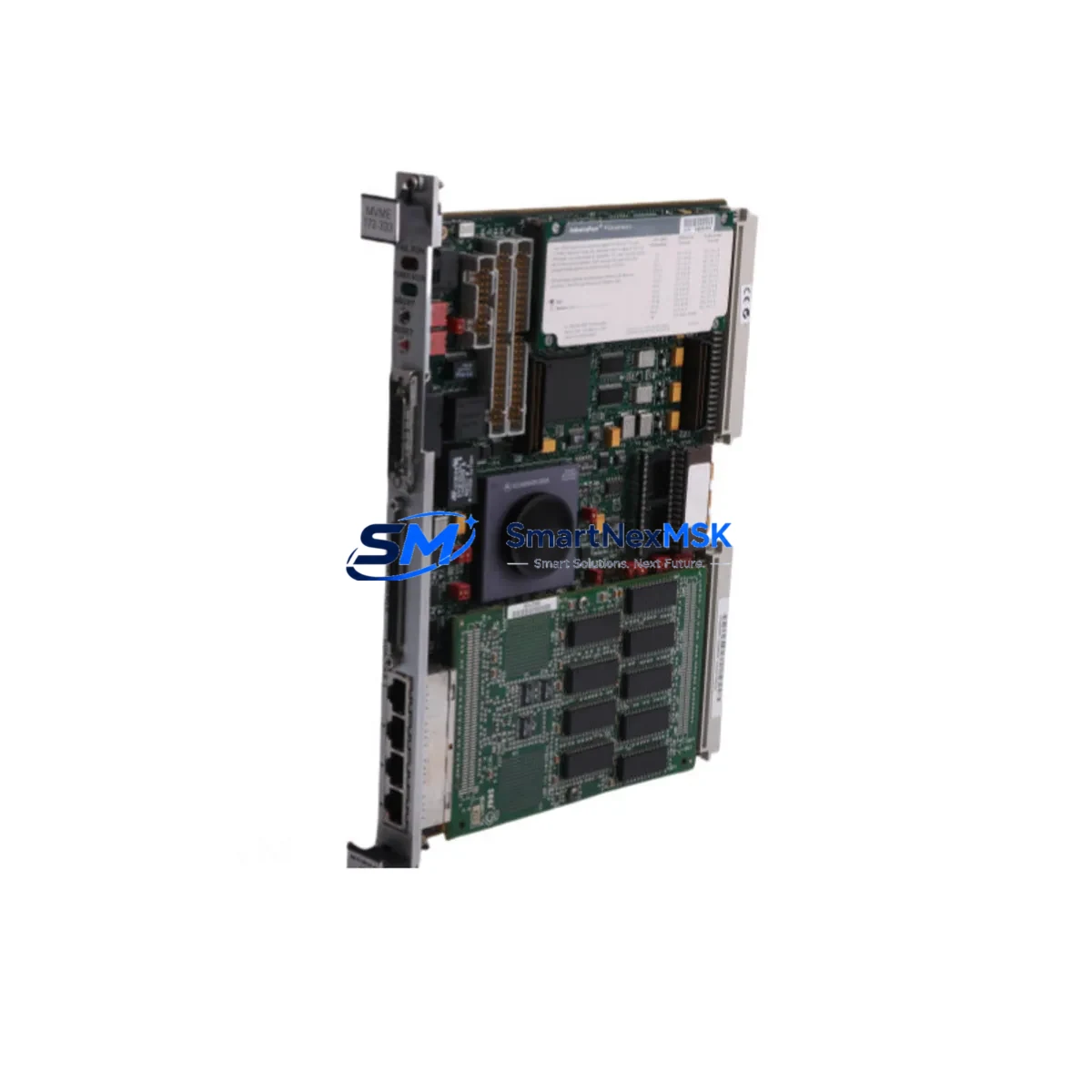
The Motorola MVME172-333 is a high-performance VMEbus Single-Board Computer (SBC) designed for demanding industrial automation and process control environments. As a retrofit-ready replacement for the MVME172 series, this module enables engineers and maintenance teams to modernize aging control architectures without the cost and risk of a full system overhaul. Whether you are replacing a discontinued spare, upgrading a legacy control cabinet, or migrating from an older VMEbus platform, the MVME172-333 delivers the processing power, I/O flexibility, and protocol compatibility required for a smooth, low-risk transition.
Built around the Motorola 68060 processor running at 33 MHz, the MVME172-333 provides substantial performance headroom over earlier MVME162 and MVME167 generation boards. Its onboard DRAM, Flash memory, and serial communication ports make it a self-contained computing node capable of running real-time operating systems such as VxWorks and OS-9, which are common in legacy factory automation and defense applications. Engineers migrating from MVME172-023 or MVME172-133 variants will find the MVME172-333 pin-compatible and firmware-compatible in most standard VME rack configurations, significantly reducing re-engineering effort.
Upgrade Compatibility Table
| Parameter | MVME172-333 (This Unit) | Typical Legacy Predecessor | Retrofit Notes |
|---|---|---|---|
| Processor | Motorola 68060 @ 33 MHz | 68040 / 68030 (MVME162/167) | Verify OS and application binary compatibility |
| VMEbus Standard | VME64 / VMEbus IEEE 1014 | VMEbus IEEE 1014 | Fully backward compatible with standard VME racks |
| Onboard Memory | Up to 32 MB DRAM + Flash | 4–16 MB DRAM | Increased memory may require OS memory map update |
| Serial Ports | 4× RS-232/RS-422 | 2–4× RS-232 | Confirm terminal block wiring and baud rate settings |
| Ethernet | 10BASE-T onboard | Optional PMC/mezzanine | Update IP configuration and network driver |
| Backplane Interface | P1 + P2 VME connectors | P1 + P2 VME connectors | Direct mechanical fit in standard 6U VME chassis |
| Module Addressing | Rotary switch configurable | Rotary / jumper configurable | Match slot address to original board configuration |
| Communication Protocol | RS-232, RS-422, Ethernet TCP/IP | RS-232, RS-422 | Protocol migration support available on request |
| Installation Form Factor | 6U VME single-slot | 6U VME single-slot | No mechanical modification required |
| Warranty | 12-Month Warranty — covers functional defects under normal industrial operating conditions | ||
Retrofit Planning for Existing Automation Systems
Successful integration of the MVME172-333 into an existing control system begins with a thorough pre-installation audit. Before removing the legacy board, document the current slot address settings using the rotary switches on the original MVME172 module. These addresses define how the VME backplane arbitrates bus access among installed cards, and any mismatch will prevent the system from booting correctly. In multi-slot chassis configurations — such as those using a Motorola MVME712M transition module or a Radstone VME carrier — the backplane pinout must be verified against the MVME172-333 P1/P2 connector map to confirm signal compatibility.
Power supply capacity is a critical checkpoint. The MVME172-333 draws power from the VME +5V and ±12V rails. Confirm that the existing power supply — whether a standalone unit or an integrated chassis PSU — can sustain the additional current demand, particularly if the retrofit also involves adding a Motorola MVME761 transition module or expanding I/O through a secondary VME crate. Undersized power supplies are a leading cause of intermittent faults after board replacement.
Terminal block wiring and serial port assignments must be carefully mapped before the new board is powered on. If the legacy system used a Motorola MVME712A or MVME712T transition module for serial and parallel I/O breakout, verify that the MVME172-333’s onboard UART channels are assigned to the same logical ports expected by the application software. Mismatched COM port assignments will cause communication failures with field devices, HMI panels, and SCADA hosts.
For sites running Wonderware InTouch or Citect SCADA as the HMI layer, the engineering team should validate that the HMI tag database references the correct PLC node address and communication driver settings after the board swap. If the original system communicated via a proprietary VMEbus protocol or a dedicated fieldbus card — such as a PROFIBUS DP master module or a DeviceNet scanner installed in an adjacent VME slot — the new board’s interrupt vector table and shared memory map must be reconfigured to match the original I/O driver expectations.
Program compatibility is another key consideration. Application code compiled for the 68040 processor will generally execute on the 68060 without recompilation, but floating-point behavior and cache coherency differences may produce subtle runtime anomalies in time-critical control loops. It is strongly recommended to perform a full functional simulation in a test rack — using a spare Motorola MVME187 or equivalent VME SBC as a reference node — before committing the MVME172-333 to live production service. This step also provides an opportunity to validate the boot sequence, confirm Flash memory programming, and verify that the real-time OS kernel loads correctly from the onboard storage.
I/O expansion requirements should be assessed as part of the retrofit scope. If the existing control cabinet relies on discrete I/O through a Motorola MVME230 or MVME340 I/O module installed in the same VME chassis, confirm that the new SBC’s DMA channels and interrupt lines do not conflict with those modules’ address ranges. Proper address decoding and interrupt priority assignment are essential for deterministic I/O response times in process control applications.
Downtime Control During System Migration
Minimizing production downtime during a VMEbus SBC replacement requires a structured migration plan executed in defined phases. The first phase is a cold-swap preparation: with the system still running on the legacy board, capture a full memory dump of the application program, configuration parameters, and any non-volatile data stored in battery-backed SRAM. This backup protects against data loss if the original board fails during the transition window and provides a reference image for post-swap verification.
The second phase is a parallel validation exercise. Where plant layout permits, configure the MVME172-333 in a bench test rack alongside the original board, connect it to a mirrored I/O simulator, and run the application program in parallel for a defined observation period — typically 24 to 72 hours. This approach allows the engineering team to compare output behavior, confirm interrupt latency, and identify any timing-sensitive routines that may require adjustment before the live cutover.
The actual board swap should be scheduled during a planned maintenance window. Power down the VME chassis following the site’s lockout/tagout procedure, remove the legacy SBC, install the MVME172-333 in the same slot, and restore power. The system should boot to the OS prompt within seconds if the Flash memory has been pre-programmed with the correct image. Confirm that all serial devices — including operator terminals, barcode readers, and remote I/O adapters — re-establish communication before releasing the system to production.
Post-swap monitoring is essential for the first 48 hours of operation. Assign a dedicated technician to observe alarm logs, communication error counters, and process variable trends. Any deviation from baseline behavior should be investigated immediately, as early detection of configuration issues prevents minor discrepancies from escalating into unplanned shutdowns. With proper preparation, most MVME172-333 retrofit projects achieve a live cutover in under four hours of planned downtime.
Retrofit Support FAQ
Q1: Is the MVME172-333 a direct drop-in replacement for the MVME172-023 and MVME172-133?
A: In most standard VME rack configurations, yes. The MVME172-333 shares the same 6U VME form factor, P1/P2 connector pinout, and 68060 processor architecture as other MVME172 variants. However, the clock speed difference (33 MHz vs. earlier variants) means that time-critical application loops should be re-validated after installation. Slot address switches must be set to match the original board’s configuration before power-on.
Q2: What commissioning steps are required after installing the MVME172-333?
A: After physical installation, verify the slot address rotary switch settings, confirm power rail voltages at the backplane connector, load the application firmware via the onboard Flash programming interface or network boot, and perform a full I/O checkout against the site’s loop test procedure. Serial port baud rates, parity settings, and handshaking parameters should be confirmed against the original system documentation before enabling field device communication.
Q3: Can the MVME172-333 communicate with legacy PROFIBUS or DeviceNet field devices?
A: The MVME172-333 itself provides RS-232, RS-422, and Ethernet interfaces. PROFIBUS DP or DeviceNet connectivity requires a dedicated fieldbus master module installed in an adjacent VME slot — such as a compatible PROFIBUS PMC card or a DeviceNet scanner module. The MVME172-333 communicates with these modules via the VMEbus backplane using shared memory or interrupt-driven data exchange, consistent with the original system architecture.
Q4: What does the 12-month warranty cover, and what is the shipping lead time?
A: The 12-month warranty covers all functional defects arising under normal industrial operating conditions, including processor, memory, serial interface, and Ethernet port failures. Physical damage caused by incorrect installation, overvoltage, or ESD is excluded. Units are shipped after pre-shipment functional testing. Standard lead time is 3–7 business days for in-stock units, with expedited options available. Global shipping is supported with full export documentation.
© 2026 SMARTNEXMSK. All rights reserved.
Original Source: https://smartnexmsk.com
Contact: sales@smartnexmsk.com | +86 18259474341