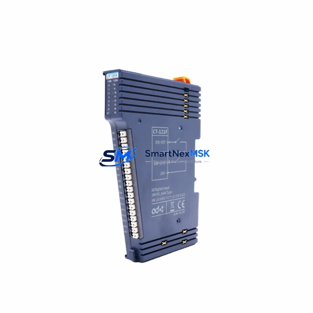
ODOT CT-121F Retrofit-Ready Distributed I/O Expansion Module for CT Series Control Systems
The ODOT CT-121F is a retrofit-ready distributed I/O expansion module engineered for seamless integration into existing CT Series automation architectures. Whether you are replacing an end-of-life I/O node, expanding a legacy control cabinet, or executing a full control system modernization, the CT-121F delivers the compatibility, reliability, and field-proven performance that industrial engineers demand. With a 12-month warranty, pre-shipment functional testing, and in-stock availability, this module is the preferred choice for minimizing downtime during planned and emergency retrofits.
Upgrade Compatibility Table
| Parameter | Details |
|---|---|
| Compatible Series | ODOT CT Series distributed I/O systems |
| Module Type | Distributed I/O Expansion Module |
| Backplane Interface | CT Series standard backplane slot — direct plug-in replacement |
| Communication Protocol | Compatible with CT Series fieldbus communication (EtherNet/IP, PROFIBUS, or Modbus RTU depending on coupler configuration) |
| Terminal Wiring | Screw-terminal block; verify existing field wiring gauge and torque spec before re-termination |
| Power Supply Requirement | Sourced from CT Series bus coupler or dedicated 24 VDC segment power; confirm segment current budget before installation |
| Module Address | Slot-based addressing; re-use existing slot assignment from replaced module — no PLC program address change required in most cases |
| Replacement Recommendation | Direct drop-in for discontinued CT-121 variants; verify I/O channel count and signal type match |
| Commissioning Notes | Perform I/O force test after installation; validate HMI tag mapping and alarm thresholds |
| Warranty | 12 months from date of shipment — covers manufacturing defects and functional failure under normal operating conditions |
Retrofit Planning for Existing Automation Systems
Successful integration of the ODOT CT-121F into a brownfield control system begins with a thorough pre-retrofit audit. Engineers should start by documenting the existing rack and backplane layout, confirming available slot positions within the CT Series I/O station, and verifying that the bus coupler — typically an ODOT CT-100 or CT-110 series coupler — has sufficient segment power capacity to support the additional I/O load. The CT-121F draws its operating power from the 24 VDC bus rail; exceeding the coupler’s rated current output will cause intermittent faults or module drop-out.
Terminal block wiring is the most time-sensitive step during a live-system swap. Field cables connected to the outgoing module should be labeled and photographed before removal. The CT-121F uses the same screw-terminal pitch as predecessor CT Series I/O modules, allowing direct re-termination without rewiring the field side. However, engineers should inspect wire ferrules and confirm that conductor cross-sections comply with the module’s rated input range.
For systems running on PROFIBUS DP, the bus coupler’s GSD file must be verified against the new module’s I/O configuration. If the CT-121F replaces a module with a different channel count, the GSD file may require updating in the PROFIBUS master — typically a Siemens S7-300, S7-400, or equivalent third-party PLC. In EtherNet/IP environments, the EDS file registered in the Logix or equivalent controller project should be reviewed to confirm that the I/O assembly size matches the CT-121F’s data footprint.
Where the control system includes an ODOT CT-200 series remote I/O coupler or a Modbus RTU gateway, the register map assigned to the replaced module must be preserved in the new configuration. Modbus register addresses are typically fixed by slot position, so a like-for-like slot replacement will maintain address continuity without requiring PLC program edits. This is a critical advantage when working on systems where the original program source code is unavailable or where re-compilation carries certification risk.
HMI screens connected to the affected I/O — whether running on a Weintek, Siemens TP series, or Advantech panel — should be tested in simulation mode before the physical swap. Tag bindings referencing the replaced module’s I/O addresses must be validated, and any alarm setpoints tied to analog input channels should be re-confirmed after the CT-121F is energized. In systems using SCADA platforms such as Ignition or WinCC, historian tags linked to the affected I/O points should be placed in manual override during the swap window to prevent false alarm logging.
For I/O expansion projects — rather than direct replacements — the CT-121F can be added to an existing CT Series station by occupying an unused backplane slot. The bus coupler will automatically enumerate the new module during its next power cycle or hot-swap detection cycle, depending on firmware version. Engineers should confirm the coupler firmware supports hot-swap before attempting live insertion. If the station is at maximum slot capacity, an additional CT Series rack extension or a second I/O station connected via the fieldbus trunk may be required, along with a supplementary 24 VDC power supply module to maintain segment power balance.
Communication cable integrity is often overlooked during retrofit planning. PROFIBUS DP segments should be checked for correct termination resistors at both ends of the trunk, and EtherNet/IP drops should be verified for cable length compliance and switch port configuration (100 Mbps full-duplex, no auto-negotiation issues). Modbus RTU installations should confirm RS-485 bias resistors and shield grounding continuity before commissioning the replacement module.
Downtime Control During System Migration
Minimizing production downtime is the primary engineering constraint in any brownfield I/O retrofit. The ODOT CT-121F supports a structured hot-swap procedure on compatible CT Series couplers, allowing the module to be replaced without de-energizing the entire I/O station. Before initiating the swap, the PLC program should be placed in a controlled hold state — outputs forced to safe positions and interlocks confirmed — to prevent uncontrolled actuator movement during the module removal window.
The recommended sequence is: (1) force all outputs on the target module to their safe state via the PLC or HMI; (2) document and photograph terminal wiring; (3) remove the outgoing module and insert the CT-121F into the same backplane slot; (4) re-terminate field cables; (5) release the PLC from hold state and perform a structured I/O force test channel by channel; (6) confirm HMI displays and historian tags are updating correctly before returning the process to automatic mode.
For systems where hot-swap is not supported, a planned maintenance window of 2–4 hours is typically sufficient for a single-module replacement, including pre-work, physical swap, re-termination, and functional verification. Pre-staging the CT-121F with correct DIP switch or configuration settings — if applicable — before the maintenance window begins will reduce in-window time significantly. All replacement modules shipped by SMARTNEXMSK undergo pre-shipment functional testing to confirm channel integrity, reducing the risk of a DOA module extending the downtime window.
Original PLC program logic does not require modification in a like-for-like slot replacement scenario. The existing ladder logic, function block diagrams, or structured text referencing the I/O addresses of the replaced module will continue to operate without recompilation, preserving program certification status and eliminating the risk of introducing software regressions during the hardware swap.
Retrofit Support FAQ
Q1: Is the ODOT CT-121F a direct drop-in replacement for discontinued CT Series I/O modules?
In most CT Series installations, the CT-121F occupies the same backplane slot and uses the same terminal block pitch as the module it replaces. Channel count and signal type (digital input, digital output, or analog) must be confirmed to match the outgoing module. Where the channel configuration differs, minor PLC program address adjustments may be required. Our technical team can assist with compatibility verification before shipment.
Q2: What commissioning steps are required after installing the CT-121F?
After physical installation and re-termination, perform a full I/O force test to verify each channel responds correctly. Confirm that the bus coupler recognizes the new module in its I/O map. Validate HMI tag bindings and alarm thresholds. For PROFIBUS systems, confirm the GSD configuration matches the new module. For EtherNet/IP systems, verify the EDS file and I/O assembly size. Document all commissioning results for maintenance records.
Q3: Does the CT-121F require any wiring changes compared to the module it replaces?
The CT-121F uses the same screw-terminal block design as standard CT Series I/O modules. Field wiring can typically be re-terminated directly without modification. Engineers should inspect wire ferrules and confirm conductor cross-sections are within the module’s rated range. Terminal labeling from the original installation should be preserved and verified against the updated wiring diagram.
Q4: What does the 12-month warranty cover, and what pre-shipment testing is performed?
Every CT-121F unit shipped by SMARTNEXMSK is functionally tested prior to dispatch to confirm channel integrity and communication response. The 12-month warranty covers manufacturing defects and functional failure under normal operating conditions from the date of shipment. Warranty claims are supported with replacement or repair. Units damaged by incorrect wiring, overvoltage, or environmental conditions outside the rated specification are not covered under the standard warranty terms.
© 2026 SMARTNEXMSK. All rights reserved.
Original Source: https://smartnexmsk.com
Contact: sales@smartnexmsk.com | +86 18259474341