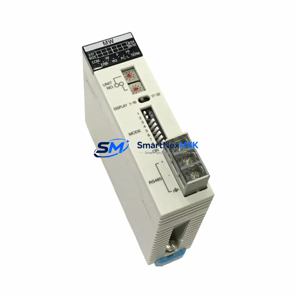
Panasonic AFP2720 Maintenance-Ready Spare for FP2 Automation
The Panasonic AFP2720 (FP2-MW) is an original master word unit designed for the FP2 series PLC platform — one of Panasonic’s most widely deployed programmable logic controller families in discrete manufacturing, process control, and factory automation environments. As a data link module, the AFP2720 enables high-speed peer-to-peer communication between FP2 CPU units and remote I/O stations, making it a critical component in distributed control architectures. When this module fails or degrades, the entire data link network can collapse, triggering unplanned downtime across multiple control zones.
Sourced as an original Panasonic spare, this AFP2720 unit is fully tested prior to shipment, covered by a 12-month warranty, and available for fast dispatch to support emergency maintenance and planned overhaul schedules alike. Whether you are managing a single-line retrofit or maintaining a multi-cabinet FP2 installation, having a verified AFP2720 in your spare parts inventory is a foundational step in any downtime-reduction strategy.
Spare Maintenance Table
| Parameter | Specification |
|---|---|
| Part Number | AFP2720 |
| Model Designation | FP2-MW (Master Word Unit) |
| Series | Panasonic FP2 |
| Module Type | PLC Data Link / Network Communication Module |
| Communication Role | Master station for FP2 data link network |
| Compatible CPU Units | FP2 CPU modules (AFP2201, AFP2202, AFP2211, AFP2431 series) |
| Backplane Compatibility | FP2 main unit and expansion backplanes |
| Installation | Slot-mount on FP2 base unit; no external power supply required |
| Operating Temperature | 0°C to 55°C |
| Origin | Japan (Original Panasonic) |
| Condition | Original, new or tested-good surplus |
| Pre-shipment Test | Function verified before dispatch |
| Warranty | 12 Months |
| Typical Application | Distributed I/O, inter-PLC data exchange, remote station control |
| Maintenance Recommendation | Inspect link status LEDs quarterly; replace on first sign of communication fault |
Maintenance Planning for Continuous Operation
When a maintenance or procurement engineer identifies the AFP2720 as a replacement requirement, the scope of inspection should extend well beyond the module itself. The FP2 data link network depends on a chain of interdependent components, and a single degraded element can mask or amplify faults elsewhere in the system.
Begin by auditing the FP2 CPU module (such as the AFP2201 or AFP2431) for firmware version compatibility and communication parameter settings — mismatched link parameters are a common cause of intermittent data link errors that are incorrectly attributed to the AFP2720. Next, inspect the FP2 backplane and expansion base units: cracked slot connectors or oxidized contacts can cause the new module to seat poorly and generate the same fault codes as the failed unit.
On the power side, verify the FP2 power supply module (AFP2800 series) is delivering stable 5 VDC to the backplane. Voltage sag under load is a leading cause of communication module resets and data link dropouts. If the cabinet also houses FP2 analog I/O modules (AFP2440 or AFP2460 series), confirm that their signal wiring is properly shielded and grounded — ground loops introduced through unshielded analog cables can corrupt the data link signal integrity.
For cabinets running mixed networks, check any FP2 PROFIBUS-DP or CC-Link interface modules installed alongside the AFP2720. These modules share backplane resources, and a failing network interface can starve the data link master of processing cycles. Similarly, inspect terminal blocks and field wiring connectors on all I/O modules in the same cabinet: loose terminations generate transient noise that propagates through the backplane and disrupts communication timing.
If the system includes an FP2 HMI interface or GT series operator panel connected via RS232C or RS485, verify the communication cable integrity and port settings. HMI communication errors are frequently misdiagnosed as data link failures. Finally, review any signal isolators or surge protection devices installed on the data link wiring runs — these components have finite service lives and should be replaced on a scheduled basis, not only on failure.
Stocking one AFP2720 per FP2 installation, alongside a spare AFP2800 power supply and a backup AFP2201 CPU module, is the minimum recommended spare parts posture for facilities where FP2-controlled lines run continuously or on multi-shift schedules.
Site Replacement Workflow
Step 1 — Preparation: Before removing the AFP2720, use the FP2 programming tool (FPWIN GR or FPWIN Pro) to export the current data link configuration parameters, including station numbers, link relay allocations, and link register assignments. Store this file on a local drive — it will be required to commission the replacement module.
Step 2 — Safe Isolation: Place the FP2 CPU in STOP mode via the programming tool or the front-panel RUN/STOP switch. Confirm all controlled outputs are in a safe state before proceeding. Do not power down the entire cabinet unless the installation requires it — the FP2 backplane supports hot-swap on some configurations, but verify this against your specific base unit model before attempting.
Step 3 — Module Exchange: Remove the AFP2720 by releasing the module locking lever and sliding it out of the backplane slot. Insert the replacement AFP2720, ensuring the connector seats fully. Verify the module’s LED indicators illuminate correctly on power-up: the LINK LED should flash during initialization and stabilize once the data link network is established.
Step 4 — Parameter Restore: Using FPWIN GR or FPWIN Pro, reload the saved data link configuration to the new module. Confirm all slave stations are recognized and that link relay and register data is exchanging correctly. Monitor the system for a minimum of 15 minutes under normal load before returning the line to production.
Step 5 — Documentation: Record the replacement date, module serial number, and post-replacement test results in the equipment maintenance log. Update the spare parts inventory to trigger reorder of a replacement AFP2720 unit, maintaining your buffer stock level.
This workflow minimizes mean time to repair (MTTR) and ensures the replacement module is correctly commissioned, reducing the risk of repeat faults caused by configuration errors.
Spare Parts Support FAQ
Q1: Is this AFP2720 compatible with all FP2 series base units?
The AFP2720 is designed for the Panasonic FP2 platform and is compatible with standard FP2 main base units and expansion bases that support communication module slots. Compatibility should be confirmed against your specific base unit model number and the FP2 hardware manual before installation. Units from the FP2 SH (super high-speed) sub-series may have different slot assignments — verify accordingly.
Q2: What pre-shipment testing is performed on this module?
Each AFP2720 unit is functionally tested prior to dispatch to verify backplane communication, LED status indication, and module initialization. Units that do not pass functional verification are not shipped. Test records are available on request for quality-critical applications.
Q3: What does the 12-month warranty cover?
The 12-month warranty covers manufacturing defects and functional failures under normal operating conditions. It does not cover damage resulting from incorrect installation, overvoltage events, or use outside the specified environmental parameters. Warranty claims are processed with return of the defective unit for inspection.
Q4: Can you support long-term or blanket orders for AFP2720 spare parts?
Yes. For facilities managing aging FP2 installations or planning multi-year maintenance contracts, we support scheduled delivery agreements and reserved stock arrangements. Contact our sales team to discuss volume pricing, lead time commitments, and inventory reservation options for AFP2720 and related FP2 series components.
© 2026 SMARTNEXMSK. All rights reserved.
Original Source: https://smartnexmsk.com
Contact: sales@smartnexmsk.com | +86 18259474341