Panasonic FP-VM-10-MO Maintenance-Ready Spare GT Series Automation
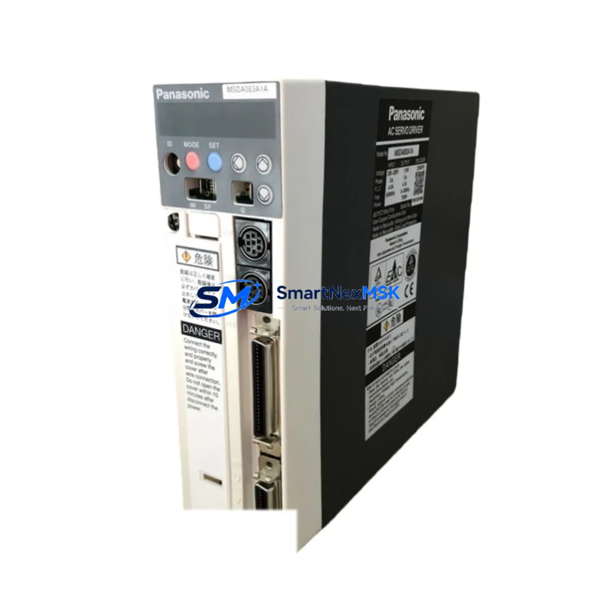
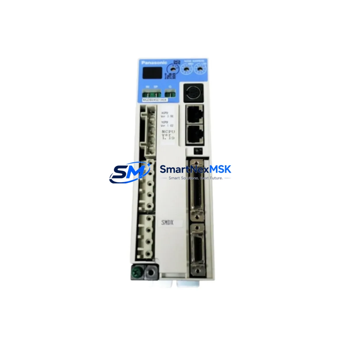
The Panasonic FP-VM-10-MO is a GT Series HMI operator interface designed for demanding industrial automation environments. As a maintenance-ready original spare, it enables maintenance and procurement engineers to execute rapid panel replacements, minimize unplanned downtime, and sustain continuous production across FP-series PLC-controlled systems. Whether you are managing a scheduled shutdown, responding to an emergency fault, or building a strategic spare parts inventory for aging control infrastructure, the FP-VM-10-MO delivers the compatibility, reliability, and verified performance that industrial sites require.
Sourced directly from authorized supply channels, every FP-VM-10-MO unit undergoes pre-shipment functional verification to confirm display integrity, communication interface operation, and power-on self-test results. This ensures that the replacement unit arrives ready for immediate installation — reducing the risk of secondary faults during a critical recovery window. A 12-month warranty is included with every shipment, providing procurement teams with the assurance needed for long-term spare parts planning.
Spare Maintenance Table
| Parameter | Specification |
|---|---|
| Part Number / SKU | FP-VM-10-MO |
| Brand | Panasonic Industrial Devices |
| Series | GT Series HMI |
| Product Type | HMI Operator Interface |
| Compatible PLC Platform | Panasonic FP Series (FP0R, FP-X, FP2SH, FP-Sigma) |
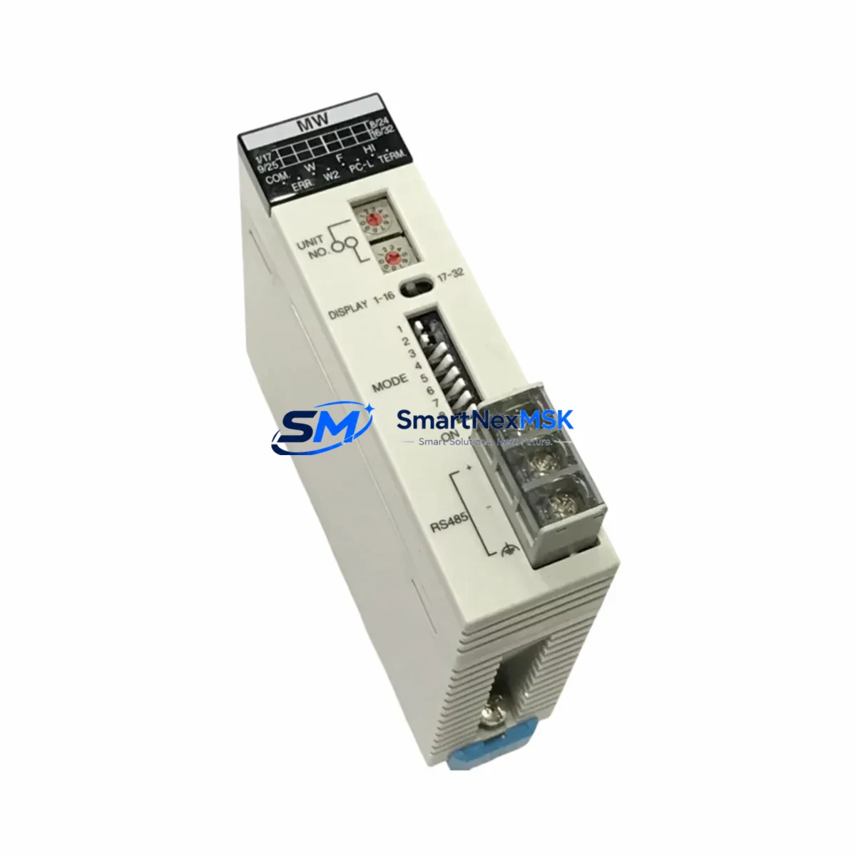
| Communication Interface | RS-232C / RS-422 (series-dependent) |
| Power Supply | 24 VDC (nominal) |
| Country of Origin | Japan |
| Installation Environment | Industrial control cabinet, panel-mount |
| Operating Temperature | 0°C to 50°C |
| Ingress Protection | IP65 (front panel, typical GT Series) |
| Maintenance Application | Direct replacement for failed or end-of-life GT Series HMI units |
| Pre-Shipment Testing | Power-on, display, and communication interface verified |
| Warranty | 12 Months |
| Availability | In stock — long-term supply supported |
Maintenance Planning for Continuous Operation
When a GT Series HMI such as the FP-VM-10-MO fails or is flagged during a routine control cabinet inspection, experienced maintenance engineers know that the HMI is rarely the only component requiring attention. A systematic inspection of the surrounding electrical circuit is essential to prevent repeat failures and ensure a clean, stable recovery.
Begin by verifying the 24 VDC power supply module feeding the HMI panel — voltage sag or ripple is a common root cause of display faults and communication dropouts. Inspect the FP-series CPU module (such as the FP0R-C32T or FP-X C60T) for error LEDs and confirm that the PLC program is intact and running. Check the RS-232C or RS-422 communication cable connecting the HMI to the PLC; damaged shielding or loose terminal connections frequently cause intermittent screen freezes that are misdiagnosed as HMI hardware failure.
Examine the digital input/output expansion modules connected to the same PLC rack — a faulty DI or analog output module can generate cascading alarms that overwhelm the HMI display buffer. Inspect relay output modules for contact wear, particularly on high-cycle actuator control circuits. Review the terminal blocks and wiring ferrules in the control cabinet for signs of oxidation, loose crimps, or thermal discoloration, which indicate sustained overload conditions.
If the system includes a communication gateway or protocol converter (for example, a MODBUS RTU to Ethernet bridge), verify its status indicators and confirm that the HMI tag database is correctly mapped. For installations with signal isolators on analog loops, test isolation integrity to rule out ground loop interference affecting HMI readings. Finally, check any miniature circuit breakers or fuses in the panel that protect the HMI power circuit — a nuisance trip caused by an aging fuse can be mistaken for an HMI hardware fault.
Maintaining a co-located spare set that includes the FP-VM-10-MO alongside a backup FP0R CPU module, a spare 24V SMPS power supply, a set of FP-X I/O expansion modules, and a spare RS-232C communication cable assembly is the most effective strategy for minimizing mean time to repair (MTTR) on Panasonic FP-series controlled lines.
Site Replacement Workflow
Step 1 — Isolate and document: Before removing the failed FP-VM-10-MO, photograph the existing wiring, communication cable routing, and panel cutout dimensions. Record the current HMI project version from the PLC program backup if accessible.
Step 2 — Power down safely: De-energize the control cabinet via the main isolator. Confirm zero-voltage on the HMI power terminals using a calibrated multimeter before disconnecting any cables.
Step 3 — Remove and inspect: Disconnect the communication cable and power connector. Remove the HMI from the panel cutout. Inspect the cutout gasket and panel surface for damage that could compromise the IP65 seal on the replacement unit.
Step 4 — Install the FP-VM-10-MO spare: Mount the replacement unit into the panel cutout, reconnect the communication cable to the correct port (verify RS-232C vs RS-422 pinout against the original wiring diagram), and reconnect the 24 VDC power supply leads.
Step 5 — Load and verify: Power up the cabinet. Confirm the HMI boots to the correct project screen. Test all operator touchpoints, alarm displays, and PLC communication tags. Run a short production cycle to validate full system compatibility before returning the line to normal operation.
This workflow applies to direct replacement of legacy GT Series HMI models and supports system continuity without requiring PLC program modifications — the preferred approach for maintenance teams managing older Panasonic FP-series installations.
Spare Parts Support FAQ
Q1: Is the FP-VM-10-MO a direct drop-in replacement for other GT Series HMI models?
The FP-VM-10-MO is designed as a GT Series HMI operator interface and is compatible with Panasonic FP-series PLC platforms using standard RS-232C or RS-422 communication. Compatibility with specific adjacent GT Series models depends on panel cutout dimensions and communication port configuration. We recommend confirming the original wiring diagram and HMI project file before installation. Our technical team can assist with compatibility verification prior to shipment.
Q2: What pre-shipment testing is performed on each unit?
Every FP-VM-10-MO unit is powered on and tested for display function, communication interface continuity, and self-diagnostic pass before packaging. Units that do not pass all checks are not shipped. A test report is available upon request for quality-critical procurement processes.
Q3: How should the FP-VM-10-MO be stored as a long-term spare?
Store the unit in its original anti-static packaging in a dry environment between 0°C and 40°C, away from direct sunlight and electromagnetic interference sources. Inspect the unit annually for any signs of capacitor aging or connector oxidation. Rotate spare stock on a first-in, first-out basis to maintain readiness.
Q4: What does the 12-month warranty cover?
The 12-month warranty covers manufacturing defects and functional failures under normal operating conditions. It does not cover damage caused by incorrect installation, overvoltage, physical impact, or unauthorized modification. Warranty claims are processed with a replacement unit dispatched after fault confirmation, minimizing additional downtime for the customer.
© 2026 SMARTNEXMSK. All rights reserved.
Original Source: https://smartnexmsk.com
Contact: sales@smartnexmsk.com | +86 18259474341