Parker GV-U6E-310 Retrofit-Ready Servo Drive for Gemini GV Series Control Systems
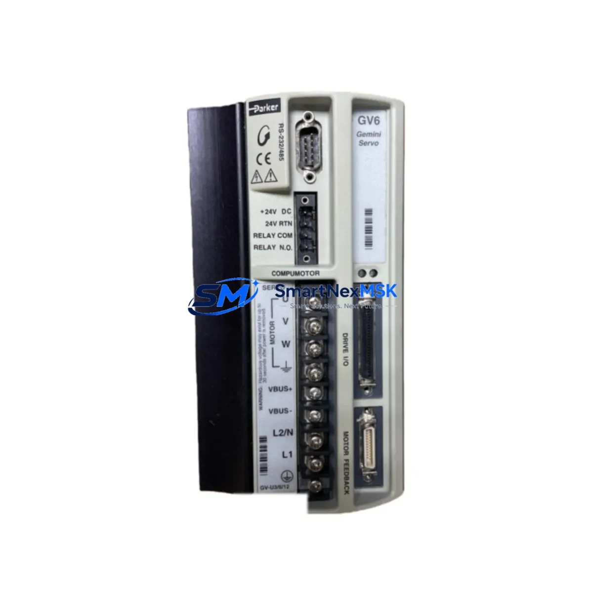
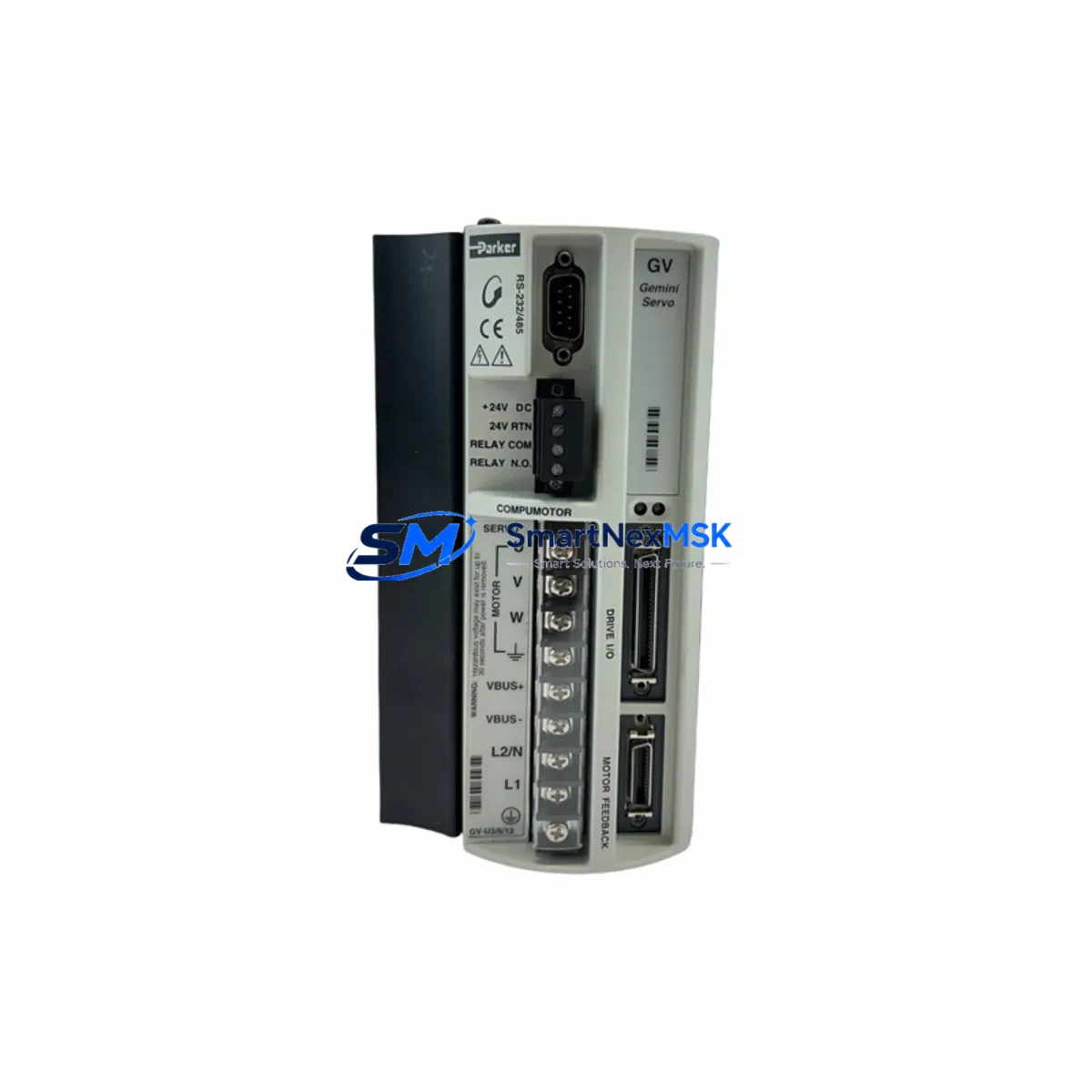
The Parker GV-U6E-310 is a high-performance servo drive from the Parker Hannifin Gemini GV series, engineered for precision motion control in demanding industrial automation environments. As legacy Gemini GV drives approach end-of-life or become increasingly difficult to source, the GV-U6E-310 remains one of the most sought-after retrofit and replacement units for existing Parker motion control architectures. Whether you are managing a planned system upgrade or responding to an unplanned drive failure, the GV-U6E-310 offers a reliable, drop-in compatible solution that minimizes engineering rework and reduces total downtime.
This unit is rated for 6A continuous output current and is designed to operate within Parker’s established Gemini GV platform, making it directly compatible with existing 310V DC bus configurations. Its onboard RS-232 and RS-485 communication ports support integration with Parker’s ACR motion controllers and legacy 6K Series controllers, preserving existing motion programs without requiring full re-commissioning. Engineers replacing a failed GV-U6E-310 or upgrading from an earlier GV-L3E or GV-U3E variant will find that the terminal layout, feedback connector pinout, and parameter structure remain consistent across the Gemini GV family.
Upgrade Compatibility Table
| Parameter | GV-U6E-310 Specification | Retrofit Notes |
|---|---|---|
| Output Current (Continuous) | 6A RMS | Verify motor nameplate current does not exceed drive rating |
| DC Bus Voltage | 310V DC | Confirm existing PSR power supply rail voltage matches |
| Feedback Interface | Encoder (incremental), Resolver optional | Check J4 feedback connector pinout against motor cable |
| Communication Ports | RS-232 / RS-485 | Compatible with ACR9000, 6K4, 6K8 controllers via serial link |
| I/O Interface | Digital I/O via J3 terminal block | Map existing enable, fault, and home signals to J3 pinout |
| Mounting / Form Factor | Panel-mount, DIN-rail compatible bracket | Footprint matches GV-U3E-310 and GV-L3E-310 for direct swap |
| Programming Interface | Parker Motion Planner / Gemini Configuration Utility | Backup existing drive parameters before replacement |
| Replacement Compatibility | GV-U3E-310, GV-L3E-310, GV-U6E-310 (same series) | Confirm firmware version compatibility with host controller |
| Warranty | 12-Month Warranty | Covered from date of shipment; includes functional test report |
Retrofit Planning for Existing Automation Systems
Successful retrofit of the GV-U6E-310 into an existing control cabinet begins with a thorough audit of the current system architecture. In most Gemini GV installations, the drive shares a common DC bus supplied by a Parker PSR power supply module, which must be verified for adequate current capacity before adding or replacing drives on the same rail. If the existing PSR-12D or PSR-24D is already operating near its rated output, a capacity upgrade may be required before the new drive can be commissioned safely.
Terminal wiring on the GV-U6E-310 follows the standard Gemini GV J1 (AC input), J2 (motor output), J3 (I/O), and J4 (feedback) connector layout. When replacing a failed unit, technicians should photograph or document all existing wiring before disconnection, paying particular attention to the enable input, fault output, and hardware limit switch signals on J3. These signals are frequently customized in legacy installations and may not match the factory default pinout described in the Gemini GV Hardware Installation Guide.
For systems controlled by a Parker 6K Series controller — such as the 6K4 or 6K8 — the drive address and axis assignment must be confirmed before power-up. The 6K controller communicates with each GV drive over a daisy-chained RS-232 or RS-485 network, and address conflicts will prevent the axis from initializing. If the system also includes a Parker ACR9000 or CompuMotor OEM750 in the same cabinet, ensure that communication port assignments do not overlap.
In multi-axis systems, the GV-U6E-310 is commonly installed alongside GV-U3E-310 drives on smaller axes and GV-U12E-310 drives on higher-torque axes, all sharing the same DC bus and control network. I/O expansion in these cabinets is often handled through a Parker ACR8020 I/O module or a third-party Beckhoff EtherCAT terminal block, which may require re-mapping if the drive replacement changes the axis numbering scheme. HMI screens built on a Parker or third-party panel PC should be reviewed to confirm that axis labels, fault codes, and jog controls reference the correct drive address after the swap.
Before final commissioning, restore the backed-up drive parameters using Parker Motion Planner or the Gemini Configuration Utility. Verify that the current loop gains, velocity loop gains, position error limits, and following error thresholds are correctly loaded. Run a no-load jog test at low speed before connecting the mechanical load, and confirm that encoder feedback direction matches the motor wiring. If the system uses a Parker SM or NeoMetric servo motor, check the motor file selection in the drive configuration to ensure the correct back-EMF constant and pole count are applied.
Downtime Control During System Migration
Minimizing production downtime during a GV-U6E-310 replacement requires preparation before the maintenance window begins. The most effective approach is to pre-configure the replacement drive offline using Parker Motion Planner, loading the saved parameter file from the failed unit or from a known-good backup. This eliminates the need for on-site parameter entry and reduces the risk of transcription errors under time pressure.
If a parameter backup is not available, the 6K Series controller or ACR9000 may retain a copy of the last downloaded motion program, which can be used to reconstruct the axis configuration. In some installations, the HMI retains axis tuning data in a recipe file that can be exported and used as a reference during re-commissioning.
For critical production lines where even a brief interruption is unacceptable, consider maintaining a pre-configured spare GV-U6E-310 on the shelf with parameters already loaded. This reduces the physical swap and verification time to under 30 minutes in most installations. All units shipped from our inventory are functionally tested prior to dispatch and include a test report confirming output current, feedback signal integrity, and communication port operation. The 12-month warranty covers the replacement unit from the date of shipment, providing assurance for both planned retrofits and emergency replacements.
After the drive is installed and wired, perform a controlled power-up sequence: enable the PSR power supply first, then enable the drive, and finally release the axis enable signal from the controller. Monitor the drive status LEDs and the 6K controller fault register during the first motion cycle to confirm that no following errors or overcurrent faults are generated. Document the commissioning results and update the cabinet wiring diagram to reflect any changes made during the retrofit.
Retrofit Support FAQ
Q: Is the GV-U6E-310 a direct drop-in replacement for the GV-U3E-310?
A: The GV-U6E-310 and GV-U3E-310 share the same mechanical footprint, connector layout, and communication interface, making the GV-U6E-310 a compatible physical replacement. However, the GV-U6E-310 is rated for 6A continuous versus 3A for the GV-U3E-310. Confirm that the motor and power supply are compatible with the higher current rating before installation. No firmware or parameter changes are required for the swap if the motor file is correctly selected.
Q: What commissioning steps are required after replacing a failed GV-U6E-310?
A: After physical installation and wiring verification, restore the drive parameter file using Parker Motion Planner. Confirm the drive address matches the axis assignment in the 6K or ACR controller. Perform a no-load jog test to verify encoder feedback direction and current loop stability. Check all I/O signals on J3 for correct operation before returning the axis to automatic mode. A full functional test report is included with each unit shipped from our inventory.
Q: Does the GV-U6E-310 support RS-485 multi-drop communication for multi-axis systems?
A: Yes. The GV-U6E-310 supports both RS-232 (point-to-point) and RS-485 (multi-drop) communication, allowing up to 16 drives to be networked on a single RS-485 bus with a Parker 6K Series or ACR9000 controller. Each drive must be assigned a unique address using the drive’s front-panel DIP switches or through the Gemini Configuration Utility. Termination resistors should be installed at both ends of the RS-485 bus to prevent signal reflections in longer cable runs.
Q: What does the 12-month warranty cover, and how is a warranty claim processed?
A: The 12-month warranty covers manufacturing defects and functional failures under normal operating conditions from the date of shipment. Each unit is functionally tested before dispatch, and a test report is included with the shipment. In the event of a warranty claim, contact our sales team with the order reference and a description of the fault. We will arrange for a replacement unit to be dispatched or provide technical support to diagnose the issue remotely. Warranty does not cover damage caused by incorrect wiring, overvoltage, or mechanical impact.
© 2026 SMARTNEXMSK. All rights reserved.
Original Source: https://smartnexmsk.com
Contact: sales@smartnexmsk.com | +86 18259474341