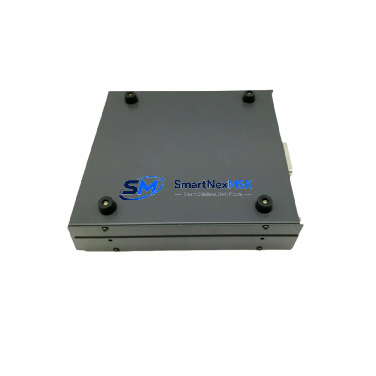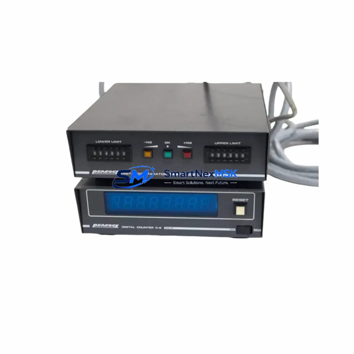
PEACOCK C-5 VER.3 Retrofit-Ready Digital Counter for C-5 Series Control Systems
The PEACOCK C-5 VER.3 is a precision retrofit-ready digital counter engineered as a direct replacement and upgrade solution for legacy C-5 Series counting systems deployed across industrial automation environments. Whether you are managing a high-speed packaging line, a press control cabinet, a batch processing unit, or a conveyor counting station, the C-5 VER.3 delivers seamless compatibility with existing wiring layouts, DIN rail mounting standards, and signal input configurations — enabling a smooth transition from discontinued or aging counter modules without requiring panel redesign or PLC program restructuring.
As industrial facilities face increasing pressure to maintain production continuity while retiring obsolete components, the C-5 VER.3 addresses the core challenges of legacy counter replacement: terminal pitch compatibility, input voltage range matching, preset value retention, and output relay logic preservation. Engineers undertaking control cabinet upgrades can verify that the C-5 VER.3 accepts the same NPN/PNP pulse inputs as the original C-5 module, supports equivalent count speeds, and retains the front-panel preset interface familiar to operators — minimizing retraining requirements and reducing commissioning time on the factory floor.
During retrofit planning, it is essential to confirm the power supply voltage feeding the counter circuit. The C-5 VER.3 operates on standard 100–240V AC or 24V DC supply configurations depending on the variant ordered, and engineers should cross-reference the existing panel wiring diagram to ensure the correct supply rail is connected. Terminal block assignments follow the original C-5 Series layout, but a point-by-point continuity check is recommended before energizing the replacement unit — particularly for the reset input, gate input, and output relay terminals. If the existing installation uses a PEACOCK PS-5 power supply module or a dedicated 24V DC bus bar, these components are fully compatible with the C-5 VER.3 and do not require replacement during the upgrade.
Upgrade Compatibility Table
| Parameter | C-5 (Legacy) | C-5 VER.3 (Replacement) | Retrofit Notes |
|---|---|---|---|
| Mounting | DIN Rail / Panel | DIN Rail / Panel | No panel modification required |
| Supply Voltage | 100–240V AC / 24V DC | 100–240V AC / 24V DC | Verify existing supply rail before wiring |
| Input Type | NPN / PNP Pulse | NPN / PNP Pulse | Direct terminal-for-terminal replacement |
| Count Speed | Up to 30 cps | Up to 30 cps | No sensor recalibration needed |
| Output | Relay (SPDT) | Relay (SPDT) | Preserve existing relay wiring |
| Communication | None / RS-232 (optional) | None / RS-232 (optional) | Confirm optional comm card if installed |
| Display | LED 6-digit | LED 6-digit | Operator interface unchanged |
| Preset Interface | Front-panel keypad | Front-panel keypad | Retain existing preset values |
| Warranty | — | 12-Month Warranty | Covered from date of shipment |
Retrofit Planning for Existing Automation Systems
A successful C-5 VER.3 retrofit begins with a thorough audit of the existing control cabinet. Before removing the legacy counter, document all terminal connections using the original wiring diagram and photograph the front-panel preset values to ensure they can be re-entered accurately after installation. In cabinets where the C-5 counter is integrated with a PEACOCK TA-5 timer module or a PEACOCK LC-5 batch controller, the signal interconnections between these units must be preserved — the C-5 VER.3 maintains the same input/output signal levels, so no intermediate signal conditioning is required.
For installations where the counter feeds a downstream PLC — such as a Mitsubishi FX3U, an Omron CP1H, or a Siemens S7-1200 — the output relay contact ratings of the C-5 VER.3 are identical to the original, ensuring that the PLC digital input module receives the same pulse or level signal without requiring changes to the ladder logic program or I/O address mapping. If the system uses a PEACOCK PR-5 preset remote unit for operator-level setpoint adjustment, this accessory is fully compatible with the C-5 VER.3 and can be reconnected without modification.
In multi-axis or multi-station counting applications, where several C-5 units are mounted on a shared DIN rail within a common enclosure, the C-5 VER.3 can be introduced one unit at a time — allowing a phased retrofit that avoids a full-line shutdown. Each replacement unit should be bench-tested prior to installation: apply the rated supply voltage, simulate pulse inputs using a signal generator or the existing sensor, verify the preset output relay operation, and confirm the reset function responds correctly. This pre-shipment bench test protocol is standard practice at SMARTNEXMSK, and every C-5 VER.3 unit is functionally tested before dispatch.
Where the original installation includes a PEACOCK CA-5 communication adapter for data logging or SCADA integration, engineers should verify the firmware version of the C-5 VER.3 to confirm compatibility with the existing communication protocol. In most cases, the RS-232 interface parameters — baud rate, data bits, stop bits, and parity — can be configured via the front-panel menu to match the legacy settings, eliminating the need to reconfigure the SCADA host or data acquisition system.
Downtime Control During System Migration
Minimizing production downtime during a counter replacement is a primary concern for maintenance engineers managing continuous or high-throughput lines. The C-5 VER.3 is designed to support a rapid swap-out procedure: with terminal connections documented and preset values recorded, a trained technician can complete the physical replacement in under 30 minutes. The unit requires no special programming tools or software — all configuration is performed via the front-panel keypad, which mirrors the interface of the original C-5 module.
To further protect production continuity, it is advisable to schedule the replacement during a planned maintenance window rather than responding reactively to a counter failure. SMARTNEXMSK maintains in-stock inventory of the C-5 VER.3, enabling same-day or next-day dispatch for urgent requirements. For facilities operating critical batch or packaging lines where counter failure would trigger a full-line stop, holding a spare C-5 VER.3 unit on-site as a cold standby is a low-cost insurance strategy that eliminates lead-time risk entirely.
During the migration, the original PLC program logic does not require modification — the C-5 VER.3 output relay behavior is functionally identical to the legacy unit. HMI screens that display counter values via PLC data registers are unaffected, as the counter-to-PLC interface remains unchanged. If the system uses a PEACOCK DP-5 digital panel meter in parallel with the counter for operator visibility, this instrument continues to operate normally throughout the replacement process.
Retrofit Support FAQ
Q1: Is the C-5 VER.3 a direct drop-in replacement for the original PEACOCK C-5?
Yes. The C-5 VER.3 is designed as a form-fit-function replacement for the C-5 Series. Terminal assignments, DIN rail footprint, supply voltage range, input signal compatibility, and output relay ratings are equivalent to the original specification. No panel modification or PLC reprogramming is required in standard retrofit applications.
Q2: What pre-shipment testing is performed on each unit?
Every C-5 VER.3 unit dispatched by SMARTNEXMSK undergoes a full functional test prior to shipment. This includes supply voltage application, pulse input simulation across the rated count speed range, preset output relay verification, reset function confirmation, and display integrity check. A test record is available upon request.
Q3: How do I verify wiring compatibility before installation?
Compare the terminal diagram of the C-5 VER.3 (supplied with the unit) against your existing wiring documentation. Key terminals to verify are: supply voltage (L/N or +24V/0V), pulse input (IN, COM), reset input (RST), gate input (GATE), and output relay (OUT1, COM, NC/NO). If your installation includes optional communication or remote preset accessories, confirm the accessory connector pinout before reconnecting.
Q4: What does the 12-month warranty cover, and what is the support process?
The 12-month warranty covers manufacturing defects and functional failures under normal operating conditions from the date of shipment. It does not cover damage resulting from incorrect wiring, overvoltage, or physical mishandling. To initiate a warranty claim, contact SMARTNEXMSK with the unit serial number, purchase date, and a description of the fault. Replacement or repair is arranged within the warranty period at no additional cost.
© 2026 SMARTNEXMSK. All rights reserved.
Original Source: https://smartnexmsk.com
Contact: sales@smartnexmsk.com | +86 18259474341