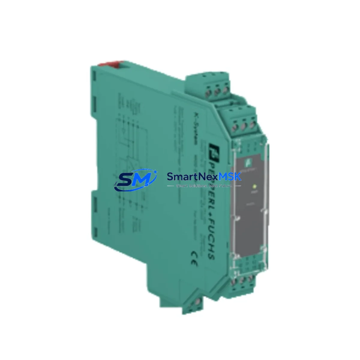
PEPPERL+FUCHS KFD2-SOT3-EX2 Retrofit-Ready Switch Amplifier for K-System Control Systems
The PEPPERL+FUCHS KFD2-SOT3-EX2 is a dual-channel, isolated switch amplifier designed for seamless integration into K-System Ex barrier installations. Whether you are replacing an end-of-life unit in a legacy DCS rack, upgrading a Fieldbus-based safety loop, or restoring a discontinued barrier in a hazardous-area control cabinet, the KFD2-SOT3-EX2 delivers verified compatibility with existing wiring, terminal assignments, and NAMUR sensor interfaces — minimizing retrofit risk and eliminating the need for panel redesign.
Sourced directly from authorized supply channels, each unit ships pre-tested and is backed by a 12-month warranty. In-stock inventory supports urgent replacement orders with fast dispatch, helping operations teams control unplanned downtime during critical maintenance windows.
Upgrade Compatibility Table
| Parameter | KFD2-SOT3-EX2 Specification | Retrofit Notes |
|---|---|---|
| Channels | 2 (dual-channel) | Direct replacement for single-channel predecessors requires wiring review |
| Input Type | NAMUR / mechanical contact | Compatible with IEC 60947-5-6 NAMUR sensors; no signal conditioner needed |
| Output | 2 × relay output (SPDT) | Verify PLC input card sink/source logic before wiring |
| Supply Voltage | 20–35 V DC (K-Bus or external) | Confirm K-System power rail capacity; add KFD2-EB2 power bus if needed |
| Mounting | DIN rail, K-System backplane | Fits standard K-System carrier; no mechanical modification required |
| Communication | Passive (relay); no fieldbus | For HART or Profibus loops, pair with KFD2-HMM-16 or gateway module |
| Hazardous Area | Zone 0/1/2, IIC, ATEX/IECEx | Verify field device Ex certification matches barrier parameters |
| Replacement Candidates | KFD2-SOT3-EX1, KFD0-SOT3-EX2 | Terminal pinout compatible; confirm output relay count |
| Commissioning | LED status indicators per channel | Test with loop calibrator before live process restart |
| Warranty | 12 Months — covers manufacturing defects, functional failure under rated conditions | |
Retrofit Planning for Existing Automation Systems
Replacing a K-System barrier in a running plant requires a structured approach that accounts for every layer of the control architecture. Before removing the legacy KFD2-SOT3-EX1 or KFD0-SOT3-EX2, engineers should document the existing terminal wiring on the K-System carrier, noting the field-side (blue terminals) and control-side (grey terminals) assignments. The KFD2-SOT3-EX2 maintains the same terminal layout, so field cable re-termination is typically not required — a significant advantage when working inside a congested hazardous-area junction box.
Power budget verification is the next critical step. The K-System backplane is powered by a dedicated supply module such as the KFD2-EB2 or KFD2-EB2.R2 power bus coupler. Adding a dual-channel unit where a single-channel module previously existed increases the current draw on the bus rail. Confirm that the installed power supply — often a KPS/24VDC/2.5A or equivalent — has sufficient headroom before energizing the new module.
On the control side, the relay outputs of the KFD2-SOT3-EX2 connect to discrete input cards on the DCS or safety PLC. If the existing system uses a Siemens S7-300 or S7-400 digital input module (e.g., SM 321), verify that the relay contact rating and the input card’s voltage threshold are compatible. For systems migrating toward S7-1500 or ET 200SP distributed I/O, the relay output interface remains unchanged, but the PLC program logic and hardware configuration (in TIA Portal) must be updated to reflect the new module address and channel mapping.
Where the legacy installation included a KFD2-HMM-16 HART multiplexer for asset management, confirm that the new barrier’s passive relay architecture does not interrupt the HART signal path. In most K-System topologies, HART communication passes through the analog barrier (e.g., KFD2-STC4-EX1) rather than the switch amplifier, so the KFD2-SOT3-EX2 replacement does not affect HART transparency.
For installations that include an HMI layer — such as a Siemens TP700 Comfort or WinCC SCADA screen — verify that the discrete input tag mapped to the barrier output is correctly associated with the new channel address. If the PLC program uses symbolic addressing, the tag database update is straightforward. Fixed absolute addressing requires a program block modification and a full download to the controller.
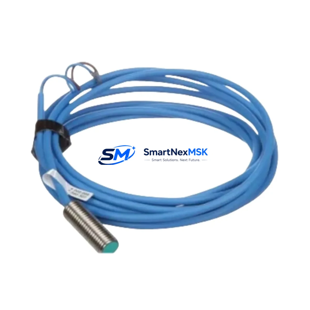
Finally, inspect the field-side cable for insulation integrity and confirm that the connected NAMUR proximity switch or mechanical contact meets the barrier’s input parameters. Pair the KFD2-SOT3-EX2 with a calibrated PEPPERL+FUCHS NBB2-12GM50-E2 or equivalent NAMUR sensor to ensure the switching threshold is within specification before returning the loop to service.
Downtime Control During System Migration
Minimizing process interruption during a K-System barrier swap requires pre-staging the replacement module, verifying all documentation, and coordinating with the operations team to schedule the changeover during a planned maintenance window. The following approach has proven effective in live plant environments:
- Pre-test the KFD2-SOT3-EX2 on a bench using a NAMUR simulator or loop calibrator before bringing it to the field. Confirm both relay outputs switch correctly at the NAMUR threshold levels.
- Back up the PLC program (S7 project or equivalent) and export the current hardware configuration before making any changes to the rack. This preserves the original logic and allows rapid rollback if the migration encounters an unexpected issue.
- Use the K-System hot-swap capability where available. The K-System carrier design allows module removal and insertion without powering down the entire backplane, provided the field loop is isolated at the field junction box first.
- Maintain control continuity by placing the affected PLC input in a forced or bypassed state during the swap interval. Document the bypass in the permit-to-work system and restore normal operation only after the new module has been verified in service.
- Perform a functional loop test end-to-end — from the field sensor through the KFD2-SOT3-EX2 to the PLC input and HMI display — before releasing the loop back to automatic control. Record the test result and retain it as part of the modification record.
With proper preparation, a single K-System barrier replacement can be completed in under 30 minutes of controlled process downtime, with no impact on adjacent loops sharing the same backplane.
Retrofit Support FAQ
Q1: Is the KFD2-SOT3-EX2 a direct drop-in replacement for the KFD2-SOT3-EX1?
Yes. The KFD2-SOT3-EX2 is the dual-channel successor to the single-channel KFD2-SOT3-EX1 and shares the same K-System carrier footprint and terminal layout. The primary difference is the addition of a second independent switch amplifier channel. If your application only requires one channel, the second channel can remain unwired without affecting performance. Confirm the control-side relay output count with your PLC I/O engineer before installation.
Q2: What wiring changes are required when replacing a KFD0-SOT3-EX2 with the KFD2-SOT3-EX2?
The KFD0-SOT3-EX2 is a legacy model with a different power supply concept (loop-powered vs. bus-powered). When migrating to the KFD2-SOT3-EX2, verify that the K-System power bus is active and that the carrier slot is compatible with the bus-powered module format. Field-side terminal wiring is typically compatible, but the control-side relay output wiring should be verified against the new module’s datasheet before energizing.
Q3: How is the KFD2-SOT3-EX2 commissioned after installation?
After seating the module in the K-System carrier and restoring power, observe the green PWR LED and the per-channel status LEDs. Use a NAMUR simulator or the connected field sensor to actuate each channel and confirm that the corresponding relay output switches and the PLC input registers the correct state. If the HMI tag does not update, check the PLC program’s I/O mapping and force a manual scan cycle. Full commissioning documentation should be retained as part of the plant modification record.
Q4: What does the 12-month warranty cover, and how is a claim processed?
The 12-month warranty covers manufacturing defects and functional failures occurring under rated operating conditions (supply voltage, ambient temperature, and load within specification). It does not cover damage resulting from incorrect installation, overvoltage, or use outside the certified hazardous-area parameters. To initiate a warranty claim, contact sales@smartnexmsk.com with the order reference, unit serial number, and a description of the failure. Replacement or repair will be arranged within the warranty period at no additional cost.
© 2026 SMARTNEXMSK. All rights reserved.
Original Source: https://smartnexmsk.com
Contact: sales@smartnexmsk.com | +86 18259474341