Pepperl+Fuchs KFD2-VM-EX1.35 Retrofit-Ready Solenoid Driver for KFD2 Series Control Systems
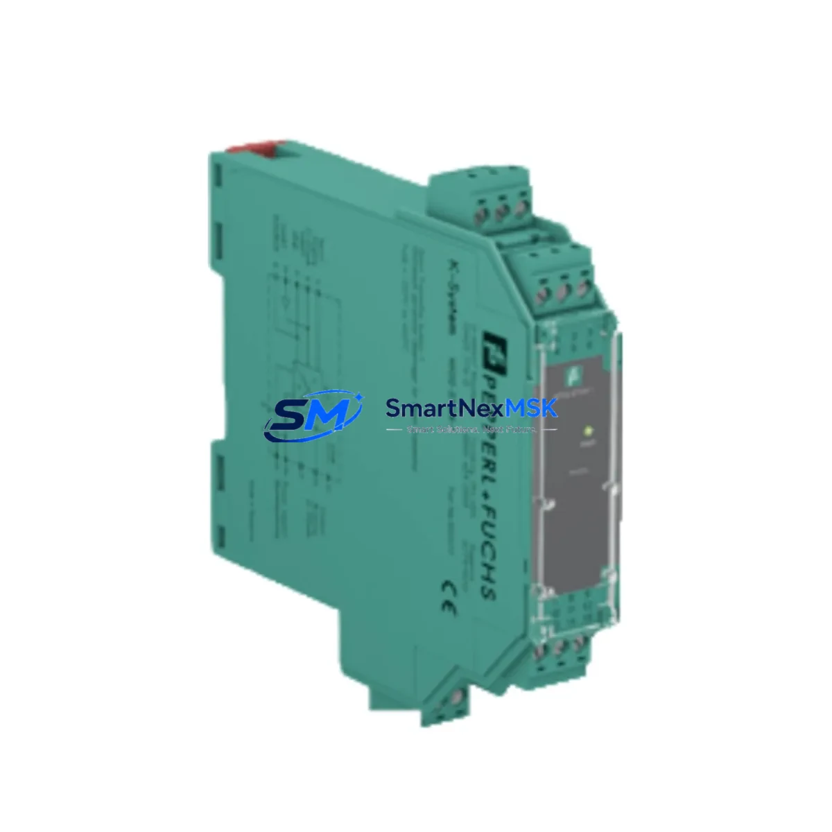
The Pepperl+Fuchs KFD2-VM-EX1.35 is a single-channel solenoid driver module engineered for intrinsically safe control of solenoid valves in Zone 1 and Zone 2 hazardous areas. As legacy DCS platforms and aging IS barrier racks reach end-of-service, the KFD2-VM-EX1.35 has become a critical retrofit component for engineers modernizing process control infrastructure without full system replacement. Its direct compatibility with the KFD2 Series DIN-rail mounting system and standard 24 V DC power rail makes it a preferred drop-in solution for brownfield upgrade projects across petrochemical, pharmaceutical, and water treatment facilities.
When planning a retrofit around the KFD2-VM-EX1.35, engineers must verify several key parameters before installation. Power supply capacity is the first checkpoint: the KFD2 Series power rail, typically fed by a KFD2-PW-1.24.1D or equivalent redundant power supply module, must have sufficient headroom to support the additional solenoid load. Terminal wiring on the field side must be confirmed against the original loop drawing — the KFD2-VM-EX1.35 uses a standard screw-terminal block compatible with 0.14–2.5 mm² conductors, and polarity must be observed on the solenoid output circuit.
Backplane interface compatibility is straightforward within the KFD2 ecosystem: the module slots directly into any standard KFD2 Series segment coupler rack without adapter hardware. However, if the existing installation uses an older KFD0 or KFD-RS series rack, a rack adapter or full rack replacement with a KFD2-GUT-Ex1.D segment coupler may be required. Module addressing is not DIP-switch based on this model — channel assignment is determined by physical slot position within the rack, which must be mapped correctly in the DCS tag database before commissioning.
Program compatibility is a key concern during migration. If the host DCS — whether a Honeywell Experion, Emerson DeltaV, ABB 800xA, or Yokogawa CENTUM — was previously interfacing with a different IS barrier type, the I/O channel configuration in the controller may need to be updated to reflect the new module’s output characteristics. Solenoid de-energize logic, fault detection thresholds, and wire-break alarm settings should all be reviewed in the DCS engineering station before the new module goes live.
HMI screen updates are often overlooked during IS barrier retrofits. If the original solenoid valve status was displayed via a hardwired discrete input fed from a separate KFD2-SR2-Ex2.W switch amplifier, that signal path remains independent of the KFD2-VM-EX1.35 replacement and does not require reconfiguration. However, if the HMI faceplate references module-level diagnostics or HART pass-through data, the engineering team should validate that the new module’s diagnostic output format matches the existing HMI driver configuration.
Communication link integrity should be verified if the KFD2 rack is connected to a KFD2-UT2-Ex1.D HART multiplexer or a segment coupler supporting PROFIBUS PA or Foundation Fieldbus. The KFD2-VM-EX1.35 does not carry HART communication natively, so any HART-enabled valve positioner in the same loop must be addressed through a separate HART-capable barrier such as the KFD2-HMM-16 or a dedicated HART modem. Confirming this topology before cutover prevents communication dropouts during the transition window.
Field commissioning for the KFD2-VM-EX1.35 follows a structured sequence: power-off the affected rack segment, remove the legacy module, insert the replacement, restore power, and verify the green LED status indicator. A loop test from the DCS — commanding the solenoid to energize and de-energize — confirms correct wiring polarity and output function. Wire-break detection should be tested by temporarily disconnecting the field terminal and confirming the fault LED activates and the DCS receives the corresponding alarm. All test results should be documented in the site commissioning record before the loop is returned to service.
For facilities managing a broader IS barrier upgrade program, the KFD2-VM-EX1.35 is frequently deployed alongside other KFD2 Series modules including the KFD2-STC4-Ex1.H temperature converter, KFD2-SR2-Ex2.W switch amplifier, and KFD2-UT2-Ex1.D universal transmitter interface. Sourcing these modules from a single supplier with verified stock and consistent lead times reduces project scheduling risk and simplifies incoming inspection. All units supplied by SMARTNEXMSK are covered by a 12-month warranty and undergo pre-shipment functional verification.
Upgrade Compatibility Table
| Parameter | Details |
|---|---|
| Module SKU | KFD2-VM-EX1.35 |
| Brand / Series | Pepperl+Fuchs / KFD2 Series |
| Function | Single-channel solenoid driver, intrinsically safe output |
| Mounting Interface | KFD2 Series DIN-rail rack, direct slot-in, no adapter required |
| Power Supply Compatibility | 24 V DC KFD2 power rail (e.g. KFD2-PW-1.24.1D) |
| Field Terminal Wiring | Screw terminals, 0.14–2.5 mm², polarity-sensitive solenoid output |
| Communication | No native HART; use KFD2-HMM-16 or KFD2-UT2-Ex1.D for HART loops |
| Hazardous Area Classification | Zone 1 / Zone 2, ATEX / IECEx certified |
| DCS Compatibility | Honeywell Experion, Emerson DeltaV, ABB 800xA, Yokogawa CENTUM |
| Replacement Recommendation | Direct replacement for KFD2-VM-EX1.35; verify rack slot position and DCS tag mapping |
| Commissioning Key Steps | Loop test, wire-break alarm verification, DCS fault acknowledgment |
| Warranty | 12-Month Warranty — all units pre-shipment tested |
Retrofit Planning for Existing Automation Systems
A successful KFD2-VM-EX1.35 retrofit begins with a thorough audit of the existing IS barrier rack. In most brownfield installations, the KFD2 rack will contain a mix of module types — solenoid drivers, switch amplifiers, temperature converters, and universal transmitter interfaces — all sharing a common power rail. Before pulling the legacy module, the project engineer should confirm that the KFD2-PW-1.24.1D power supply module has sufficient current capacity to support the replacement without triggering an overload condition on the shared rail.
Terminal block labeling should be photographed and cross-referenced against the loop drawing before any wiring is disturbed. The KFD2-VM-EX1.35 uses the same terminal layout as most KFD2 Series modules, but field wiring from older installations may use non-standard color coding or undocumented jumper configurations. If the installation includes a KFD2-GUT-Ex1.D segment coupler or a KFD2-EB termination board, the module swap can be completed without disturbing field wiring — a significant advantage for minimizing loop downtime.
I/O expansion during the retrofit window is a common request. If the control system requires additional solenoid channels beyond what the existing rack supports, a secondary KFD2 rack segment can be added using a standard KFD2-GUT-Ex1.D coupler and populated with additional KFD2-VM-EX1.35 units. The new segment must be assigned unique slot addresses in the DCS I/O configuration, and the corresponding HMI faceplates must be updated to reflect the expanded channel count. Programming cables such as the KFD2-USB-RS485 adapter may be required if the DCS engineering station does not have direct Ethernet access to the IS barrier rack.
For sites migrating from older Pepperl+Fuchs KFD0 or Z787 series barriers to the KFD2 platform, a full rack replacement is typically required. The new KFD2 rack accepts standard 35 mm DIN rail mounting and can be installed in the same control cabinet footprint in most cases. The KFD2-VM-EX1.35 is the recommended solenoid driver for this migration path, and it can be commissioned alongside other KFD2 Series modules including the KFD2-SR2-Ex2.W for discrete input signals and the KFD2-STC4-Ex1.H for thermocouple and RTD inputs, allowing the entire IS barrier layer to be standardized on a single platform.
Downtime Control During System Migration
Minimizing unplanned downtime is the primary operational constraint in any IS barrier retrofit. For the KFD2-VM-EX1.35, the physical module swap can typically be completed in under 15 minutes per channel if the replacement unit is on-site and pre-tested. SMARTNEXMSK ships all KFD2-VM-EX1.35 units with a pre-shipment functional test report, allowing site engineers to confirm module health before the maintenance window begins.
To protect original program logic during the cutover, the DCS engineer should place the affected solenoid loop in manual mode and confirm the valve is in its safe de-energized position before removing the legacy module. This prevents spurious valve actuation during the swap and ensures that the control program’s last commanded state is preserved in the DCS controller memory. Once the new module is installed and the loop test is complete, the loop can be returned to automatic mode without requiring a controller restart or program download.
Field control continuity is maintained by sequencing the retrofit one channel at a time within a multi-channel rack. Adjacent channels on the same KFD2 power rail segment remain operational during a single-slot module swap, provided the power rail is not interrupted. If the maintenance plan requires a full rack power-down, the outage window should be coordinated with the process control team to ensure all affected solenoid valves are confirmed in their safe positions and all relevant DCS alarms are suppressed for the duration of the work.
Post-installation, a 24-hour monitoring period is recommended before closing the maintenance work order. During this period, the DCS historian should be reviewed for any unexpected fault alarms, wire-break events, or solenoid output anomalies that could indicate a wiring issue or module configuration mismatch. SMARTNEXMSK’s technical support team is available to assist with commissioning questions for all supplied units within the 12-month warranty period.
Retrofit Support FAQ
Q: Is the KFD2-VM-EX1.35 a direct drop-in replacement for the original Pepperl+Fuchs module of the same part number?
A: Yes. The KFD2-VM-EX1.35 is an OEM-equivalent replacement. It uses the same KFD2 Series rack interface, terminal layout, and electrical specifications as the original. No wiring modifications or rack adapters are required for a like-for-like swap within an existing KFD2 Series installation.
Q: What commissioning steps are required after installing the replacement module?
A: After physical installation, perform a DCS-commanded loop test to verify solenoid energize/de-energize function, confirm the green status LED is active, and test wire-break detection by temporarily opening the field terminal. Document all results in the site commissioning record before returning the loop to automatic control.
Q: Can the KFD2-VM-EX1.35 be used in a rack that also contains HART-enabled modules?
A: Yes, but the KFD2-VM-EX1.35 itself does not support HART communication. HART-enabled devices in the same rack — such as valve positioners connected through a KFD2-HMM-16 HART multiplexer — operate independently and are not affected by the presence of the solenoid driver module.
Q: What warranty coverage is provided, and does it include pre-shipment testing?
A: All KFD2-VM-EX1.35 units supplied by SMARTNEXMSK are covered by a 12-month warranty from the date of shipment. Each unit undergoes pre-shipment functional verification, and a test report is included with the delivery documentation. Warranty claims are supported directly by SMARTNEXMSK’s technical team.
© 2026 SMARTNEXMSK. All rights reserved.
Original Source: https://smartnexmsk.com
Contact: sales@smartnexmsk.com | +86 18259474341