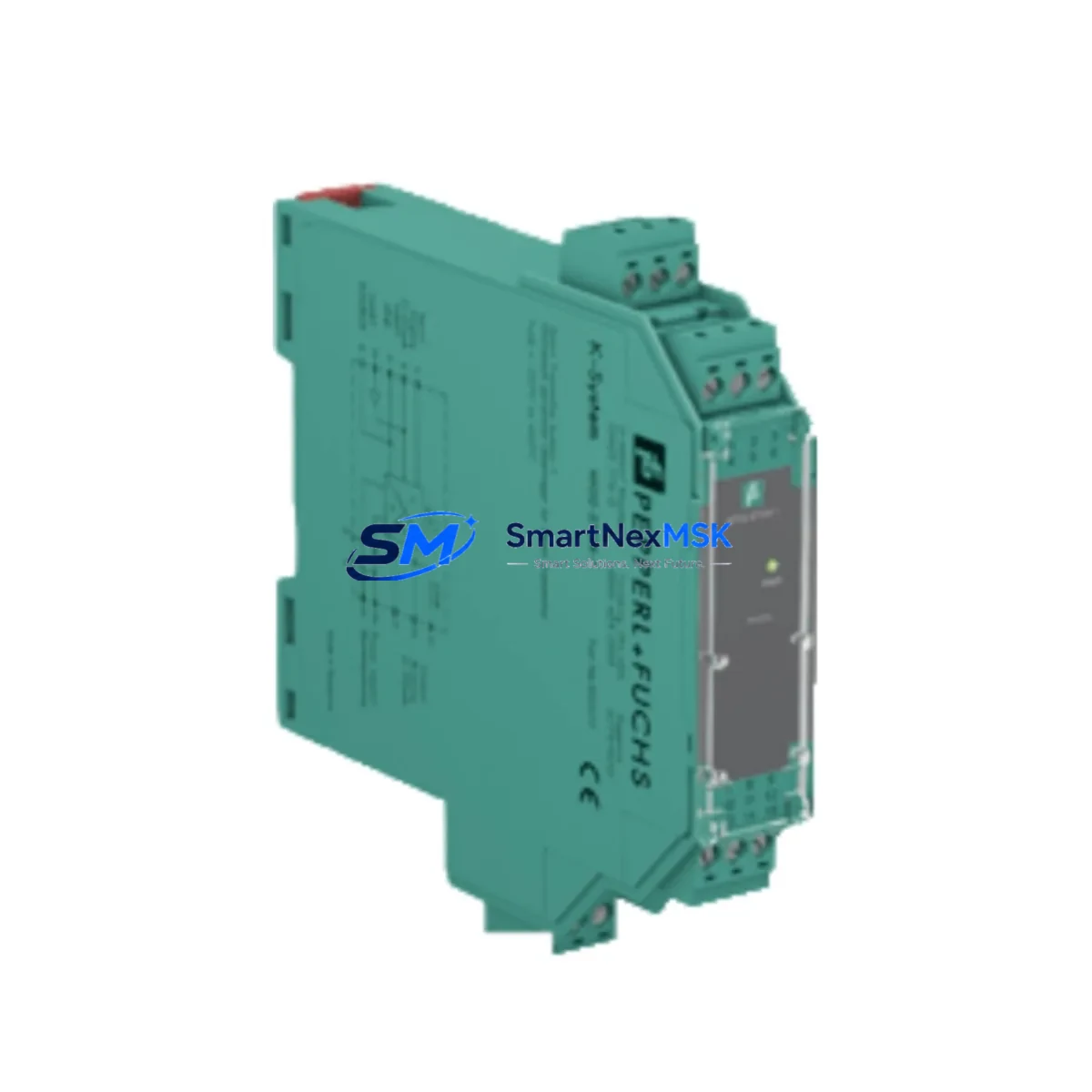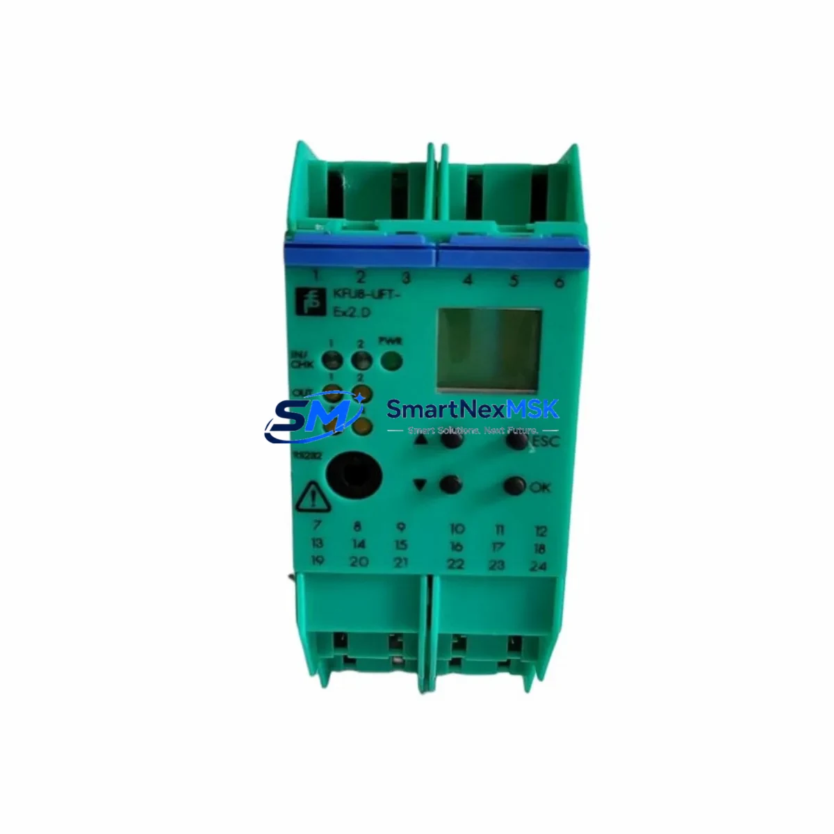
Pepperl+Fuchs KFU8-UFT-EX2.D Retrofit-Ready Frequency Transducer for KFU8 Series Control Systems
The Pepperl+Fuchs KFU8-UFT-EX2.D is a universal frequency transducer engineered for seamless integration into existing KFU8 Series control architectures. Designed to accept NAMUR-compliant proximity switch signals from hazardous Ex Zone 1 and Zone 2 environments, this module converts frequency inputs into standardized analog output signals (0–20 mA / 4–20 mA) suitable for direct connection to DCS analog input cards, PLC I/O modules, and SCADA front-end processors. For facilities managing aging control infrastructure, the KFU8-UFT-EX2.D represents a proven, specification-matched retrofit path that eliminates the need for full panel redesign.
Whether you are replacing a discontinued KFU8-series barrier, upgrading a legacy Pepperl+Fuchs K-System rail assembly, or migrating signal conditioning from an older DIN-rail enclosure to a modern marshalling cabinet, the KFU8-UFT-EX2.D maintains backward compatibility with existing terminal wiring, DIN-rail mounting footprints, and power bus configurations. This makes it a preferred choice for brownfield retrofit projects where minimizing downtime and preserving existing cable schedules are critical engineering constraints.
Each unit ships fully tested against factory specifications and is covered by a 12-month warranty. Stock is maintained for immediate dispatch, supporting both emergency replacement orders and planned maintenance shutdowns.
Upgrade Compatibility Table
| Parameter | KFU8-UFT-EX2.D Specification | Retrofit Notes |
|---|---|---|
| Input Signal Type | NAMUR / Mechanical Contact | Compatible with existing NAMUR proximity switches; no rewiring required |
| Output Signal | 0–20 mA / 4–20 mA (selectable) | Direct replacement for legacy KFU8-series analog output barriers |
| Supply Voltage | 20–30 V DC (KFU8 power rail) | Compatible with existing KFU8-IVI1.D power feed modules; verify bus capacity |
| Hazardous Area Rating | Ex ia IIC / Zone 1 & Zone 2 | Maintains existing Ex certification; no re-certification required for like-for-like swap |
| DIN Rail Mounting | 35 mm DIN rail (EN 60715) | Drop-in fit on existing KFU8 rail assemblies; no panel modification needed |
| Terminal Wiring | Screw terminals, 0.14–2.5 mm² | Matches legacy terminal pitch; existing cable schedule preserved |
| Communication Compatibility | Analog 4–20 mA loop | Compatible with HART-enabled DCS AI cards and standard PLC analog input modules |
| Replacement Recommendation | Direct replacement for KFU8-UFT-EX1.D, KFU8-UFT-EX2 | Verify output range jumper setting before commissioning |
| Commissioning Focus | Output range, frequency scaling, loop calibration | Confirm DCS/PLC scaling parameters match new module output range |
| Warranty | 12 Months | Covers manufacturing defects; includes pre-shipment functional test report |
Retrofit Planning for Existing Automation Systems
Successful integration of the KFU8-UFT-EX2.D into a brownfield control system requires a structured pre-retrofit assessment. Begin by auditing the existing KFU8 rail assembly: confirm the power supply capacity of the KFU8-IVI1.D power feed module, as adding or replacing frequency transducers may alter the total current draw on the 24 V DC bus. If the existing bus is operating near capacity, a supplementary KFD2-STC4-Ex1.2O or equivalent isolated power conditioner may be required to maintain stable supply voltage across all barrier modules.
Next, verify the field-side wiring. The KFU8-UFT-EX2.D accepts two-wire NAMUR sensors directly, but if the existing installation uses mechanical contact inputs or voltage-type proximity switches, the input configuration jumper must be repositioned accordingly. Review the existing cable schedule against the module’s terminal assignment diagram before disconnecting any field wiring. In installations where the KFU8-FSSP2.D segment protector or a KFD2-EB2 termination board is used, confirm that the new module’s terminal numbering aligns with the existing marshalling layout.
On the control system side, the KFU8-UFT-EX2.D’s 4–20 mA output connects directly to the analog input channel of the host PLC or DCS. If the host system uses a Siemens S7-300 or S7-400 platform with SM 331 analog input modules, verify that the input channel is configured for current measurement mode and that the scaling parameters in the function block (FC105 or equivalent) reflect the new module’s frequency-to-current transfer function. For systems migrating from older Pepperl+Fuchs KFA6 or KFD2 series barriers, note that the output impedance and loop resistance specifications may differ, requiring adjustment of the PLC analog input card’s load resistance settings.
HMI screen updates should be planned in parallel with the hardware swap. If the existing SCADA or HMI (such as a Siemens WinCC or FactoryTalk View station) displays frequency-derived process values, confirm that the engineering unit conversion tags reference the correct input range. A mismatch between the module’s output scaling and the HMI tag configuration is a common source of post-retrofit alarm nuisance and process value drift.
For installations involving PROFIBUS DP or PROFINET remote I/O racks, the KFU8-UFT-EX2.D feeds into the analog input card of the remote station rather than directly into the fieldbus node. Ensure the remote I/O rack’s IM 153 or equivalent interface module firmware is compatible with the analog card revision in use, and that the GSD/GSDML file loaded in the engineering tool (Step 7 or TIA Portal) accurately reflects the current hardware configuration.
Downtime Control During System Migration
Minimizing production downtime during a KFU8-UFT-EX2.D swap requires a disciplined hot-swap or planned-outage strategy. For non-Ex installations or where the process permits brief signal interruption, the module can be replaced during a scheduled maintenance window without powering down the entire control panel. Isolate the affected channel at the DCS/PLC by placing the analog input in manual override or forcing the tag to a safe fallback value before disconnecting the field wiring. This prevents spurious alarms, interlock trips, or unintended actuator responses during the swap interval.
Before removing the existing module, photograph or document the terminal wiring connections, noting wire colors, cable labels, and any ferrule markings. Retain the original cable schedule and compare it against the KFU8-UFT-EX2.D terminal diagram to confirm pin-for-pin compatibility. Reconnect field wiring in the same sequence, tighten terminals to the specified torque (typically 0.5–0.6 Nm for this terminal size), and verify continuity before restoring power to the module.
After power restoration, perform a loop calibration check: inject a known frequency signal at the field terminals using a calibrator and verify that the 4–20 mA output at the control system end corresponds to the expected engineering value. Update the DCS/PLC tag from manual override to automatic control only after confirming that the live process value matches the expected reading within the acceptable tolerance band. This structured commissioning sequence protects the original program logic, preserves interlock integrity, and ensures that the control system resumes normal operation without residual configuration errors.
Retrofit Support FAQ
Q1: Is the KFU8-UFT-EX2.D a direct drop-in replacement for the KFU8-UFT-EX1.D?
In most installations, yes. Both modules share the same DIN-rail footprint, terminal pitch, and power bus interface. The primary difference is the output range configuration: the EX2.D supports dual-range output (0–20 mA and 4–20 mA selectable via jumper), while the EX1.D is factory-set to a single range. Verify the output jumper position before commissioning and confirm that the DCS/PLC analog input scaling matches the selected output range.
Q2: What wiring checks are required before installing the KFU8-UFT-EX2.D in an Ex Zone 1 area?
Confirm that the field-side cable is rated for the hazardous area classification (Ex ia IIC or equivalent), that cable glands are appropriately certified, and that the total capacitance and inductance of the field loop do not exceed the module’s safe parameters (Ci and Li values stated in the EC type examination certificate). Do not modify field wiring while the zone is classified as hazardous without following the site’s hot-work permit procedure.
Q3: How do I verify compatibility with my existing DCS analog input card?
The KFU8-UFT-EX2.D outputs a standard 4–20 mA current loop signal. It is compatible with any DCS or PLC analog input card that accepts 4–20 mA inputs with a load resistance of up to 500 Ω. Check the input card’s datasheet for maximum loop resistance and confirm that the total loop resistance (including cable resistance) falls within the module’s specified load range. For HART-enabled cards, the module’s analog output is HART-transparent, allowing HART communication to pass through if a HART-capable field device is connected upstream.
Q4: What does the 12-month warranty cover, and is a pre-shipment test report available?
The 12-month warranty covers manufacturing defects in materials and workmanship from the date of shipment. Each unit undergoes a pre-shipment functional test verifying input sensitivity, output accuracy, and power consumption against factory specifications. A test report is available upon request. Warranty claims are processed through our sales team; contact sales@smartnexmsk.com with the order reference and a description of the observed fault.
© 2026 SMARTNEXMSK. All rights reserved.
Original Source: https://smartnexmsk.com
Contact: sales@smartnexmsk.com | +86 18259474341