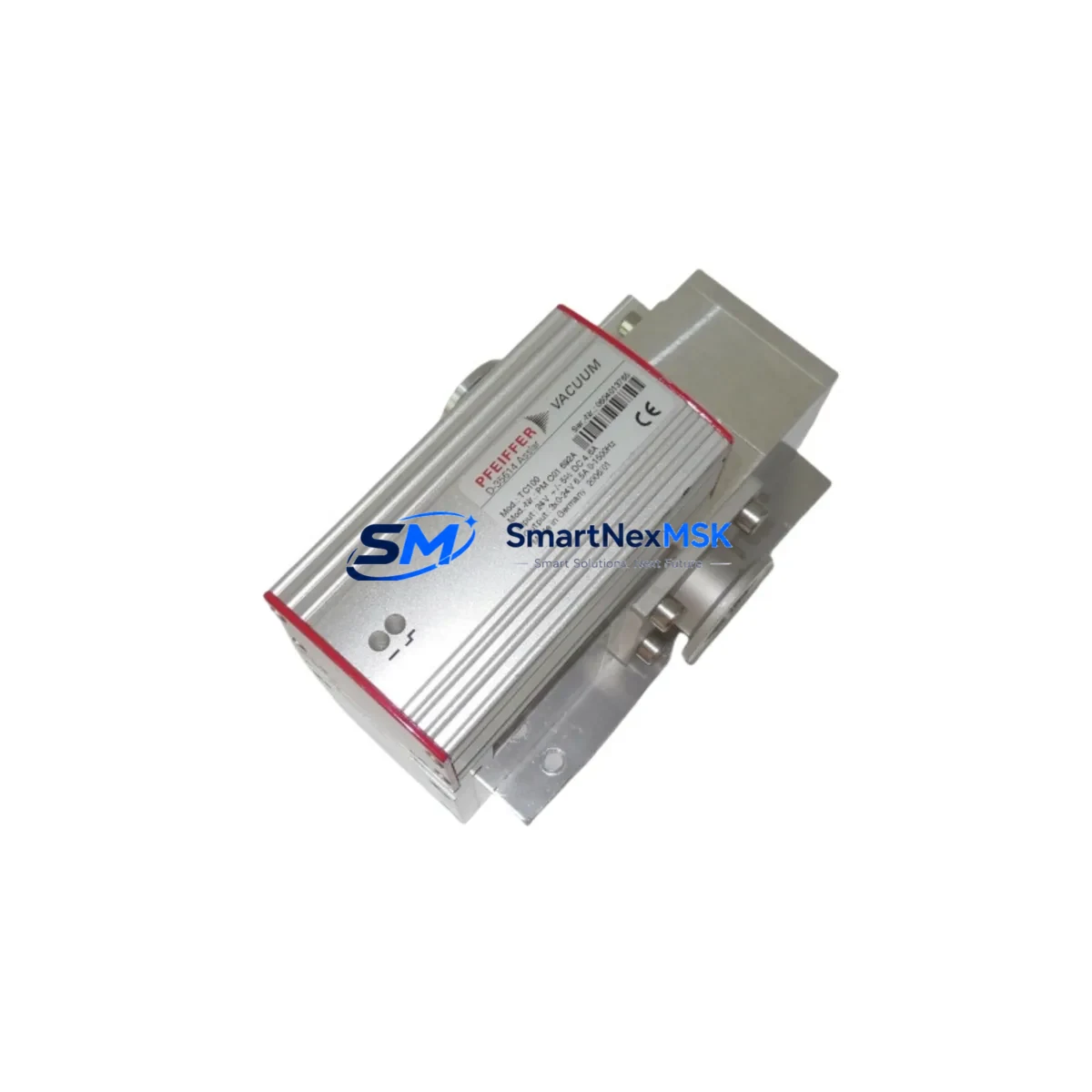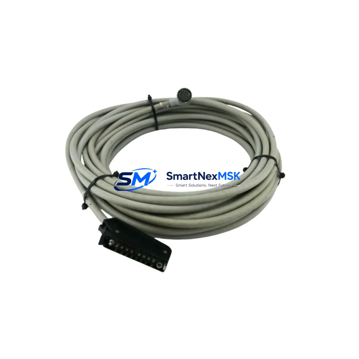
PFEIFFER VACUUM PM 011 515-T Spare for HiPace Automation: Spare Replacement & Downtime Risk Control
The PFEIFFER VACUUM PM 011 515-T (also referenced as 0040-95475 / 0190-35278) is a 15-metre turbomolecular pump drive cable engineered for direct integration with PFEIFFER VACUUM HiPace and TMH series turbomolecular pumps. In semiconductor fabs, analytical instrumentation labs, coating systems, and high-vacuum research environments, this cable forms the critical signal and power link between the pump body and its dedicated frequency converter or drive electronics. Cable degradation, connector fatigue, or insulation breakdown in this component can bring an entire vacuum process line to an unplanned standstill — making a verified, ready-to-ship spare an essential element of any preventive maintenance programme.
This listing supplies an original PFEIFFER VACUUM PM 011 515-T drive cable, sourced through authorised industrial channels, pre-shipment tested for continuity and insulation integrity, and backed by a 12-month warranty against manufacturing defects. Each unit is individually packaged to prevent connector damage during transit and is available for fast global dispatch.
Spare Maintenance Table
| Parameter | Specification |
|---|---|
| Part Number | PM 011 515-T |
| Cross-Reference SKU | 0040-95475 / 0190-35278 |
| Brand | PFEIFFER VACUUM |
| Cable Length | 15 Metres |
| Compatible Series | HiPace, TMH Turbomolecular Pump Series |
| Function | Drive signal & power interconnect between pump and frequency converter |
| Connector Type | OEM-matched multi-pin shielded connectors (both ends) |
| Insulation Rating | Suitable for industrial vacuum environments; shielded against EMI |
| Origin | Germany (DE) |
| Condition | Original New / Tested |
| Pre-Shipment Test | Continuity check, insulation resistance, connector seating verified |
| Application Environment | Semiconductor, analytical, coating, R&D high-vacuum systems |
| Installation | Direct OEM replacement; no modification required |
| Warranty | 12 Months from date of shipment |
| Shipping | Secure anti-static packaging; fast global dispatch |
Maintenance Planning for Continuous Operation
When a maintenance or procurement engineer schedules replacement of the PM 011 515-T drive cable, best practice demands a concurrent inspection of all interdependent components within the same vacuum control cabinet and pump circuit. Overlooking adjacent wear items during a planned cable swap is one of the most common causes of repeat unplanned downtime within 30–90 days of a maintenance event.
Begin with the PFEIFFER VACUUM TC 110 or DCU 110 frequency converter — the drive electronics unit that the PM 011 515-T cable connects to. Inspect its front-panel status LEDs, check for error codes logged in its memory, and verify that the converter’s output voltage and frequency are within specification before reconnecting a new cable. A faulty converter will damage a replacement cable within hours of restart.
Next, inspect the pump-side D-sub or circular connector housing on the HiPace pump body itself. Bent pins, oxidised contacts, or cracked connector shells are frequently the root cause of intermittent drive faults that are misdiagnosed as cable failures. Replacement connector kits or pump-side interface boards (such as the PM 061 261 or equivalent interface PCB for your HiPace variant) should be held in the same spare parts kit as the drive cable.
The 24 VDC auxiliary power supply feeding the frequency converter deserves attention during every cable replacement. Voltage sag or ripple on the 24 V rail — often caused by an ageing DIN-rail power supply module — can produce erratic pump speed behaviour that mimics cable faults. A replacement 24 V PSU module rated for the converter’s standby and run current should be stocked alongside the PM 011 515-T.
For systems using the PFEIFFER VACUUM RVC 300 or DCU 300 remote vacuum controller, verify that the RS-485 or RS-232 communication cable between the controller and the frequency converter is undamaged and properly terminated. Communication cable degradation can prevent the controller from reading pump speed or pressure data even after a successful drive cable replacement. Stocking a spare PM 011 590 or equivalent RS-485 interface cable is advisable for sites running multiple HiPace pumps.
Backing pump interconnects also warrant inspection. The fore-vacuum hose assembly and its KF or ISO-K flange seals (O-rings, centring rings) should be checked for elastomer degradation whenever the turbopump is accessed for maintenance. Replacing the PM 011 515-T cable while the system is open is the ideal moment to swap aged KF25 or KF40 O-ring and centring ring sets — low-cost consumables that prevent costly atmospheric ingress events.
Finally, review the venting valve solenoid and its wiring harness. On HiPace systems, the vent valve is typically controlled through the frequency converter’s digital output. A sticking or slow-responding vent valve can cause pump over-speed events during shutdown sequences, accelerating bearing wear and potentially damaging the drive cable through transient overcurrent. Holding a spare PM 016 288 or equivalent vent valve assembly in the maintenance store is a recognised best practice for high-uptime vacuum systems.
Site Replacement Workflow
Step 1 — Controlled Shutdown: Initiate a controlled pump-down stop via the frequency converter or remote controller. Allow the rotor to decelerate to rest (typically 5–15 minutes for HiPace models) before venting the system to atmosphere through the designated vent valve. Never disconnect the PM 011 515-T cable while the rotor is spinning — doing so will trigger an immediate fault and may damage the converter output stage.
Step 2 — Isolation and Lockout: Isolate mains power to the frequency converter at the cabinet isolator. Apply lockout/tagout (LOTO) per site safety procedures. Confirm zero-energy state with a calibrated voltage tester on the converter’s mains terminals before touching any wiring.
Step 3 — Cable Removal: Disconnect the PM 011 515-T at both ends — the converter-side connector first, then the pump-side connector. Note the cable routing and any cable management clips or conduit entries for reinstallation reference. Inspect the removed cable for visible damage: chafing, crush marks, connector pin damage, or heat discolouration near the pump body (which may indicate a bearing thermal event).
Step 4 — New Cable Installation: Route the replacement PM 011 515-T along the same path as the original, maintaining minimum bend radius and avoiding contact with hot surfaces or sharp cabinet edges. Seat the pump-side connector first, ensuring the locking ring or latch engages fully. Connect the converter-side connector and verify the locking mechanism. Restore cable management clips.
Step 5 — Functional Verification: Restore power and perform a controlled pump start. Monitor the frequency converter display for ramp-up speed progression and confirm the pump reaches its rated speed (typically 1,500 Hz rotor frequency for HiPace 80–300 models) within the expected time window. Log the replacement in the equipment maintenance record with the new cable’s serial number and installation date.
This workflow minimises total downtime to under two hours for a planned replacement and under four hours for an emergency swap — preserving process continuity and protecting the broader vacuum system investment.
Spare Parts Support FAQ
Q1: Is the PM 011 515-T compatible with all HiPace turbomolecular pump models?
The PM 011 515-T is designed for PFEIFFER VACUUM HiPace and TMH series pumps that use the standard multi-pin drive cable interface. Compatibility should be confirmed against your specific pump model number and the frequency converter variant (TC 110, DCU 110, or DCU 300). Cross-reference part numbers 0040-95475 and 0190-35278 are accepted equivalents. If your system uses an older TMH or TPH series pump with a different connector standard, please contact us with your pump serial number for compatibility verification before ordering.
Q2: What pre-shipment testing is performed on each PM 011 515-T cable?
Every PM 011 515-T unit undergoes a three-point pre-shipment inspection: (1) full-length conductor continuity check across all signal and power cores, (2) insulation resistance measurement to confirm no inter-conductor leakage, and (3) physical connector seating and locking mechanism verification at both ends. A test record is retained for each unit. The 12-month warranty covers defects identified during installation or normal operation within the warranty period.
Q3: How should the PM 011 515-T be stored as a long-term spare?
Store the cable coiled loosely (minimum 150 mm coil diameter) in its original anti-static packaging, in a dry environment between 10°C and 40°C, away from UV light, ozone sources, and chemical vapours. Connector caps should remain in place until installation. Under these conditions, the cable’s electrical and mechanical properties remain stable for a minimum of five years in storage. Inspect connector contacts annually for oxidation if stored in humid environments.
Q4: What is the lead time and warranty coverage for the PM 011 515-T?
In-stock units ship within 1–3 business days via tracked international courier. The 12-month warranty runs from the date of shipment and covers manufacturing defects in materials and workmanship. Warranty claims are supported by replacement or refund at our discretion. For sites requiring guaranteed next-day availability, we recommend holding one PM 011 515-T as an on-site critical spare — particularly for single-pump systems where downtime directly impacts production output.
© 2026 SMARTNEXMSK. All rights reserved.
Original Source: https://smartnexmsk.com
Contact: sales@smartnexmsk.com | +86 18259474341