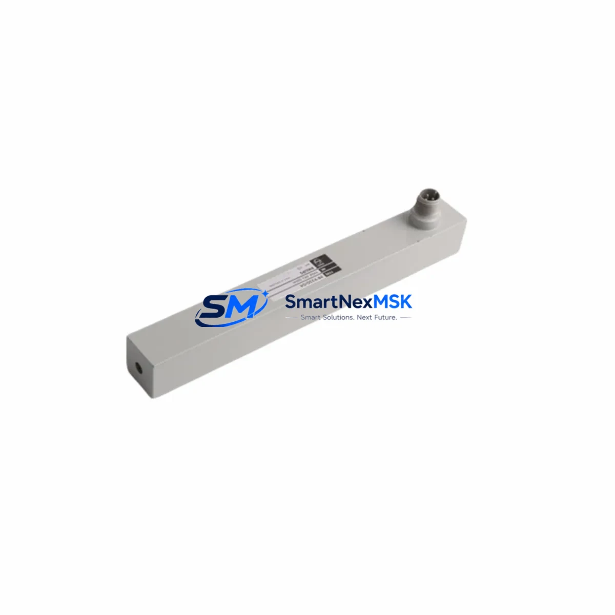
Philips LD5001M Retrofit-Ready Linear Transducer for LD Series Control Systems
The Philips LD5001M is a precision linear displacement transducer engineered for seamless integration into legacy LD Series control architectures. As industrial facilities face increasing pressure to modernize aging automation infrastructure without full system overhauls, the LD5001M provides a validated, drop-in retrofit path that preserves existing wiring harnesses, signal conditioning circuits, and PLC input configurations. Whether you are replacing a failed unit on a production line or executing a planned upgrade of a multi-axis measurement system, the LD5001M delivers the dimensional accuracy and signal stability required for demanding industrial environments.
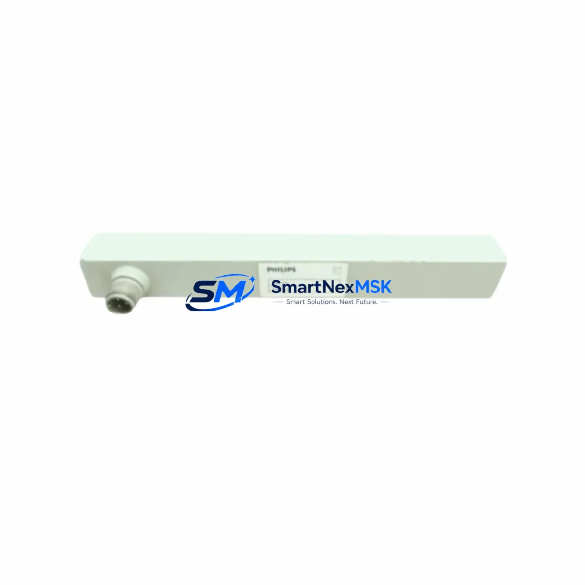
Facilities operating legacy Philips LD Series measurement systems frequently encounter obsolescence challenges: original transducers are discontinued, spare parts inventories are exhausted, and sourcing equivalent components from secondary markets introduces unacceptable quality risk. The LD5001M addresses this directly by maintaining full backward compatibility with the LD Series signal chain, including the analog output interface, mechanical mounting envelope, and connector pinout. Engineers responsible for retrofit planning can proceed with confidence that the LD5001M will not require modifications to existing cable assemblies or signal conditioning modules.
Upgrade Compatibility Table
| Parameter | Detail |
|---|---|
| Compatible Series | Philips LD Series linear displacement systems |
| Mounting Interface | Standard LD Series mechanical envelope; no bracket modification required |
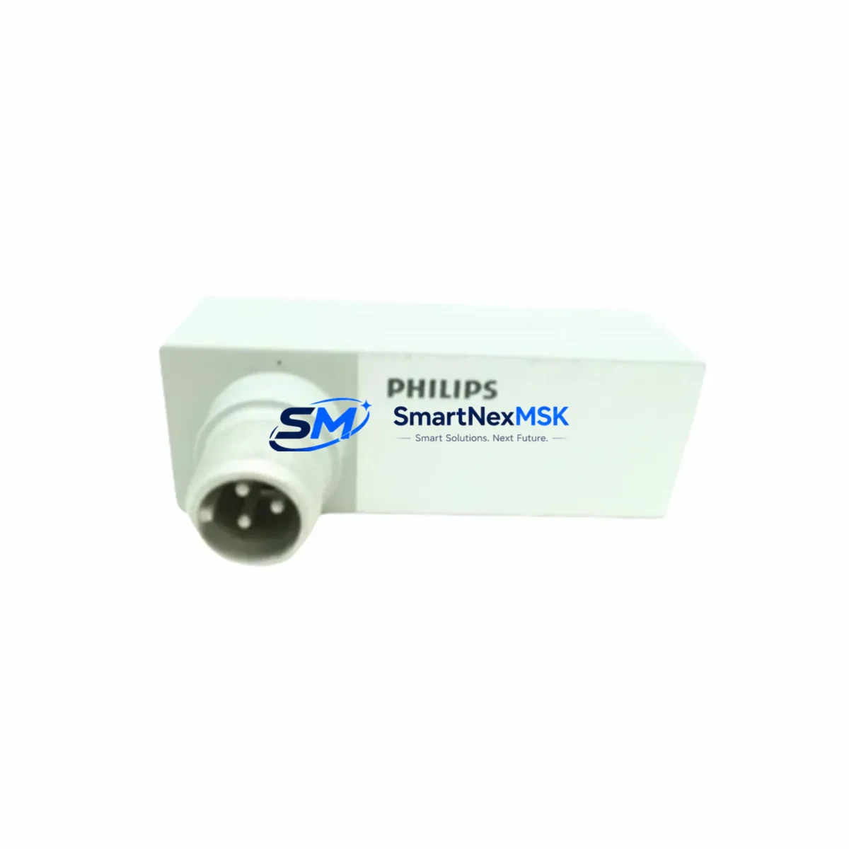
| Electrical Connector | Compatible with original LD Series cable assembly and pinout |
| Signal Output | Analog (compatible with existing LD Series signal conditioners) |
| Communication Compatibility | Analog signal chain; integrates with PLC analog input modules without protocol changes |
| Replacement Recommendation | Direct drop-in for discontinued LD Series transducers; verify stroke length against application spec |
| Commissioning Notes | Confirm zero-point calibration and span adjustment after installation; re-verify HMI scaling if applicable |
| Warranty | 12-Month Warranty — covers manufacturing defects under normal operating conditions |
Retrofit Planning for Existing Automation Systems
A successful LD5001M retrofit begins well before the unit arrives on site. Engineers should audit the existing control cabinet to confirm that the power supply module delivering excitation voltage to the transducer is within specification — an undersized or aging power supply can introduce measurement drift even with a new transducer installed. The terminal block wiring should be photographed and documented before disconnection, as the LD5001M uses the same pinout as its predecessors, but field modifications made over years of operation may have introduced non-standard connections.
The backplane or rack housing the PLC analog input module should be inspected for corrosion or loose card-edge contacts. In systems where the LD Series transducer feeds directly into a dedicated analog input card, the input range configuration stored in the PLC program must be verified to match the LD5001M output characteristics. If the facility uses a distributed I/O architecture — for example, remote I/O expansion modules mounted near the measurement point — the field wiring between the remote I/O node and the transducer should be tested for continuity and insulation integrity before the new unit is energized.
Communication links between the PLC and supervisory systems also warrant attention during retrofit planning. Facilities running PROFIBUS DP or Modbus RTU networks should confirm that the analog input module’s node address and baud rate settings are preserved after any rack or module swap. Where the measurement data feeds an HMI display, the tag mapping and engineering unit scaling should be validated against the LD5001M’s output range to prevent erroneous readings on operator screens. Programming cables used for online diagnostics — such as those connecting a laptop to the PLC’s programming port — should be available on site during commissioning to allow real-time monitoring of the analog input value as the transducer is calibrated.
For facilities upgrading multiple measurement points simultaneously, a staged approach is recommended: replace one transducer, complete calibration and functional verification, then proceed to the next. This approach limits exposure and allows the maintenance team to identify any system-specific anomalies before they propagate across the entire measurement network. Spare terminal blocks, cable glands, and shielded signal cables should be staged in the control room before work begins to avoid delays caused by missing consumables.
Downtime Control During System Migration
Minimizing production downtime during a transducer replacement requires a structured pre-outage preparation protocol. Before the planned maintenance window, the existing PLC program should be backed up in full — including all data blocks, function blocks, and hardware configuration files — to a secure offline location. This backup protects against accidental program loss during any online configuration changes and provides a recovery baseline if commissioning reveals unexpected compatibility issues.
During the outage window, the LD5001M should be installed and mechanically secured before any electrical connections are made. Once wiring is complete and verified against the documented terminal layout, the system should be powered up in a controlled sequence: excitation supply first, then the PLC rack, then the analog input module. The raw analog input value should be monitored in real time via the programming interface before the HMI is brought online, allowing the commissioning engineer to confirm that the transducer is producing a valid signal across its full stroke range.
If the facility’s control system includes a safety interlock or position-based permissive that references the transducer output, these interlocks should be temporarily bypassed — under a formal permit-to-work — during the calibration phase, then re-enabled and functionally tested before the system is returned to production. Documenting the as-found and as-left calibration values provides a traceable record for maintenance management systems and supports future planned maintenance intervals. With proper preparation, a single-transducer replacement using the LD5001M can typically be completed within a standard 4-hour maintenance window, preserving production continuity and avoiding unplanned extended outages.
Retrofit Support FAQ
Q: Is the LD5001M a direct replacement for all discontinued Philips LD Series transducers?
A: The LD5001M is designed as a retrofit-compatible replacement within the LD Series family. Customers should verify the stroke length and mechanical mounting dimensions against their specific application before ordering. Our technical team can assist with cross-reference confirmation based on the original part number.
Q: Will I need to modify my PLC program or analog input scaling after installing the LD5001M?
A: In most cases, no program modification is required if the LD5001M output range matches the original transducer. However, we recommend verifying the analog input scaling in the PLC configuration and confirming HMI tag engineering units after installation. A brief online calibration check using the programming cable is standard practice.
Q: What wiring checks should be completed before energizing the replacement unit?
A: Confirm terminal block connections against the original wiring documentation, verify cable shield grounding at the control cabinet end, and test insulation resistance on the signal cable before connection. Ensure the excitation voltage from the power supply module is within the LD5001M’s specified input range prior to energizing.
Q: What does the 12-month warranty cover, and is pre-shipment testing performed?
A: Every LD5001M unit undergoes functional output testing prior to shipment. The 12-month warranty covers manufacturing defects and component failures under normal operating conditions. Units showing damage resulting from incorrect wiring, overvoltage, or mechanical overload are not covered. Warranty claims are supported with a straightforward RMA process and priority replacement dispatch.
© 2026 SMARTNEXMSK. All rights reserved.
Original Source: https://smartnexmsk.com
Contact: sales@smartnexmsk.com | +86 18259474341