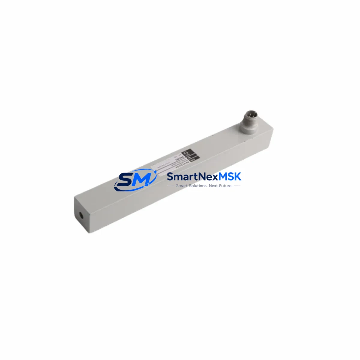
PHILIPS SDM010 Retrofit-Ready Signal Drive Module: Compatible Upgrade for SDM Series Control Systems
The PHILIPS SDM010 is a retrofit-ready signal drive control module engineered for seamless integration into legacy SDM Series automation architectures. As industrial facilities face increasing pressure to modernize aging control infrastructure without full system overhauls, the SDM010 provides a direct, wiring-compatible replacement path that minimizes engineering risk, reduces downtime, and preserves existing program logic. Whether you are replacing a discontinued SDM Series module, upgrading a control cabinet, or migrating from an obsolete communication protocol, the SDM010 is designed to slot into your existing backplane with minimal reconfiguration.
Sourced directly from verified supply channels and tested prior to shipment, each SDM010 unit is backed by a 12-month warranty covering manufacturing defects and functional failures under normal operating conditions. Stock is maintained for fast global dispatch, making the SDM010 a reliable choice for both emergency replacements and planned retrofit projects.
Upgrade Compatibility Table
| Parameter | Details |
|---|---|
| Compatible Series | PHILIPS SDM Series control systems |
| Module Type | Signal Drive Control Module |
| Backplane Interface | SDM Series standard backplane slot — direct plug-in replacement |
| Terminal Wiring | Wiring-compatible with original SDM Series terminal layout; verify field wiring polarity before power-up |
| Communication Compatibility | Compatible with SDM Series communication bus; confirm protocol version with engineering documentation |
| Installation Requirement | No mechanical modification required; confirm rack slot addressing before insertion |
| Replacement Recommendation | Direct drop-in for discontinued SDM Series signal drive modules; cross-reference OEM part number before ordering |
| Commissioning Focus | Verify module address configuration, I/O channel mapping, and HMI tag binding after installation |
| Warranty | 12-Month Warranty — covers manufacturing defects and functional failures under normal operating conditions |
| Origin | China (CN) |
| Weight | 1,680 g |
Retrofit Planning for Existing Automation Systems
Successful integration of the SDM010 into a legacy control system begins with a thorough pre-retrofit audit. Engineers should document the existing rack configuration, including the backplane model, occupied slot addresses, and the power budget of the installed power supply module. In many SDM Series installations, the system power supply — often a dedicated DC bus power module — must be verified to support the additional load introduced by a replacement signal drive module, particularly in high-density I/O configurations.
Before removing the original module, capture a full backup of the controller program using the appropriate programming cable or engineering workstation software. For systems running on older PHILIPS SDM Series controllers, the program backup should include all function block configurations, I/O force tables, and retentive data registers. This ensures that if the replacement module triggers any address conflict or configuration mismatch, the original logic can be restored without data loss.
Terminal block wiring should be photographed and labeled before disconnection. In retrofit scenarios involving I/O expansion — for example, adding additional analog input channels alongside the SDM010, or integrating supplementary digital output modules — the terminal strip layout may need to be extended. Confirm that the existing DIN rail and control cabinet have sufficient physical space for any additional I/O modules or communication modules being added as part of the upgrade scope. When expanding I/O capacity, engineers frequently pair the SDM010 with SDM Series analog input modules and digital output modules mounted in adjacent rack slots to maintain a unified backplane address space.
Communication link integrity is a critical checkpoint. If the SDM Series system uses a fieldbus protocol such as PROFIBUS DP or a proprietary PHILIPS communication bus, the SDM010 must be configured with the correct station address and baud rate before going online. In systems where an HMI panel — such as a PHILIPS operator panel or a third-party touch panel connected via RS-485 or Ethernet — is linked to the controller, HMI screen tags referencing the replaced module’s I/O addresses must be verified and updated if the new module uses a different memory mapping. Communication gateway modules or protocol converters are commonly deployed alongside the SDM010 in facilities migrating from legacy serial fieldbus architectures to modern Ethernet-based control networks.
For facilities migrating from legacy serial communication protocols to modern Ethernet-based architectures, the SDM010 retrofit may be accompanied by the installation of a communication gateway module or protocol converter. In such cases, the programming cable used during commissioning should be compatible with the engineering software version installed on the maintenance laptop. Confirm that the firmware version of the SDM010 is supported by the current version of the PHILIPS programming environment before beginning online configuration. Engineers working on multi-axis drive systems may also need to verify compatibility between the SDM010 and any servo drive modules or variable frequency drive interface cards installed in the same control cabinet.
Rack and backplane integrity should also be inspected during the retrofit. Aging backplane connectors, corroded rack guides, or damaged slot contacts can cause intermittent faults even with a new module installed. If the existing rack shows signs of wear, consider replacing the backplane assembly or the full rack chassis as part of the upgrade scope to ensure long-term reliability. In high-availability installations, a spare SDM010 unit and a spare rack power supply module should be kept on-site to support rapid recovery in the event of an unplanned failure.
Downtime Control During System Migration
Minimizing production downtime during a signal drive module replacement requires careful pre-staging and a structured cutover plan. Begin by staging the SDM010 on a bench test setup — if available — to verify basic functionality, LED status indicators, and communication response before bringing the module to the production floor. Pre-configure the module address and any DIP switch or software settings in advance so that installation time on the live system is reduced to a physical swap and wiring reconnection.
Where the control system architecture permits, use the controller’s online change or partial download capability to push updated I/O configuration to the CPU without a full program stop. This approach preserves the execution of unaffected program sections and maintains control continuity for outputs not associated with the replaced module. For systems that do not support online changes, schedule the cutover during a planned maintenance window and prepare a rollback procedure using the pre-captured program backup. In distributed control architectures where the SDM010 operates alongside remote I/O stations or distributed I/O modules connected via a fieldbus segment, ensure that the fieldbus master is placed in a safe state before removing the original module to prevent spurious output activations.
During the physical swap, use ESD precautions when handling the SDM010 to prevent electrostatic damage to the module’s signal conditioning circuitry. After insertion, power up the rack and observe the module’s diagnostic LEDs before enabling field outputs. Confirm that the controller recognizes the new module at the correct slot address and that no fault codes are generated in the system diagnostic log. Once the module is online, perform a functional test of each I/O channel associated with the SDM010 before returning the system to automatic operation. Where the system includes a SCADA interface or data historian connected to the controller, verify that data acquisition tags associated with the SDM010’s I/O points are updating correctly before signing off on the migration.
Document the completed retrofit in the facility’s maintenance records, including the replacement date, module serial number, firmware version, and any configuration changes made during commissioning. This documentation supports future troubleshooting and ensures continuity if a different engineer performs maintenance on the system at a later date.
Retrofit Support FAQ
Q1: Is the SDM010 a direct replacement for the original PHILIPS SDM Series signal drive module?
The SDM010 is designed as a retrofit-compatible replacement for SDM Series signal drive modules. It shares the same backplane interface and terminal wiring layout as the original series. However, customers should cross-reference the OEM part number and confirm slot address compatibility with their specific rack configuration before ordering. Our technical team can assist with cross-reference verification prior to shipment.
Q2: What commissioning steps are required after installing the SDM010?
After physical installation, verify the module address configuration matches the slot assignment in the controller program. Check I/O channel mapping in the engineering software, confirm HMI tag bindings if applicable, and test each field signal connected to the module before enabling automatic control. For systems with fieldbus communication, confirm the station address and baud rate settings before going online. If the system includes a communication module or protocol gateway in the same rack, verify that the fieldbus segment is stable and free of address conflicts before completing commissioning.
Q3: Can the SDM010 be used in systems with mixed I/O modules and communication modules from the same SDM Series rack?
Yes. The SDM010 is designed to coexist with other SDM Series modules in a shared rack environment, including digital I/O modules, analog I/O modules, and communication modules installed in adjacent slots. Confirm the total power budget of the rack power supply supports the combined load of all installed modules before finalizing the retrofit configuration. In racks where a high-density analog input module or a multi-channel digital output module is already installed, pay particular attention to the backplane current draw to avoid overloading the power supply module.
Q4: What does the 12-month warranty cover, and how is it processed?
The 12-month warranty covers manufacturing defects and functional failures under normal operating conditions from the date of shipment. Each unit undergoes pre-shipment functional testing before dispatch. In the event of a warranty claim, contact our sales team with the order reference and a description of the fault. Replacement or repair will be arranged promptly to minimize impact on your operations.
© 2026 SMARTNEXMSK. All rights reserved.
Original Source: https://smartnexmsk.com
Contact: sales@smartnexmsk.com | +86 18259474341