Phoenix Contact 2866763 Retrofit-Ready PSU for QUINT POWER Control Systems
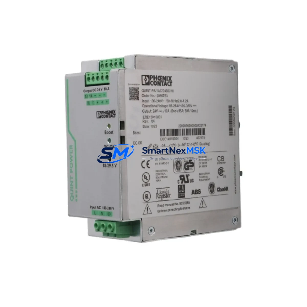
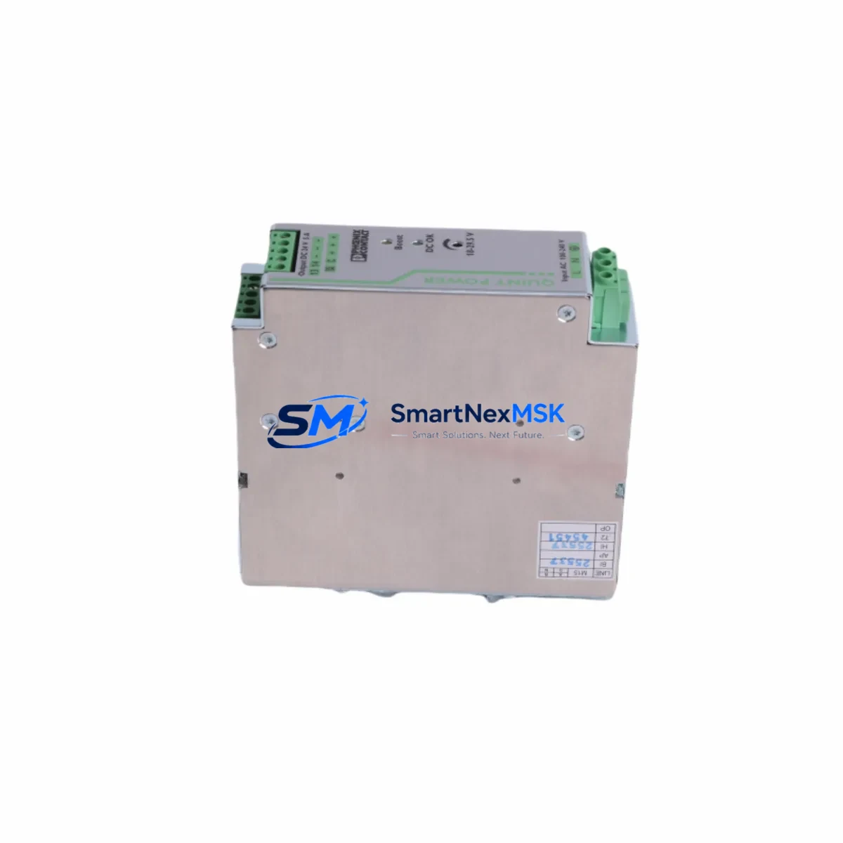
The Phoenix Contact 2866763 QUINT-PS/1AC/24DC/10 is a 240 W, 24 VDC / 10 A single-phase DIN rail power supply engineered for seamless integration into existing QUINT POWER control architectures. Whether you are replacing an end-of-life unit in a legacy panel, upgrading a brownfield automation line, or restoring a critical control cabinet after an unplanned failure, the 2866763 delivers the electrical performance and form factor required for a drop-in retrofit without re-engineering the surrounding infrastructure.
Industrial facilities running older Phoenix Contact QUINT-PS variants — including the QUINT-PS/1AC/24DC/5 and QUINT-PS/1AC/24DC/20 — frequently encounter obsolescence challenges as original units reach end-of-production. The 2866763 occupies the same DIN rail footprint, uses identical 24 VDC output bus wiring, and maintains backward compatibility with the QUINT POWER series terminal block layout, making it the preferred replacement path for maintenance engineers who need to minimize panel re-work and avoid costly re-certification.
Before committing to a retrofit, engineers should verify several key parameters: confirm that the existing 24 VDC bus load does not exceed 10 A continuous draw; check that the upstream AC supply breaker is rated for the inrush current profile of the QUINT-PS topology; and inspect the output terminal wiring for correct cross-section (typically 1.5–4 mm² for 10 A loads). The 2866763 uses Phoenix Contact’s Push-in CAGE CLAMP terminal technology, which is compatible with the wiring already present in most QUINT POWER installations, eliminating the need to re-terminate field cables.
Upgrade Compatibility Table
| Parameter | Detail |
|---|---|
| SKU / Order No. | 2866763 |
| Model | QUINT-PS/1AC/24DC/10 |
| Input Voltage | 85–264 VAC, 1-phase (universal input) |
| Output Voltage | 24 VDC (adjustable 18–29.5 VDC) |
| Output Current | 10 A continuous |
| Output Power | 240 W |
| Mounting | 35 mm DIN rail (EN 60715) |
| Terminal Type | Push-in CAGE CLAMP (compatible with legacy QUINT wiring) |
| Communication | Signal contact (DC OK relay output) — compatible with existing PLC digital input wiring |
| Replaces | QUINT-PS/1AC/24DC/10 (earlier production batches), compatible upgrade path from QUINT-PS/1AC/24DC/5 with load re-assessment |
| Commissioning Note | Verify output voltage trim pot setting after installation; default factory set to 24.0 VDC |
| Warranty | 12 Months — covers manufacturing defects, output regulation failure, and terminal integrity |
Retrofit Planning for Existing Automation Systems
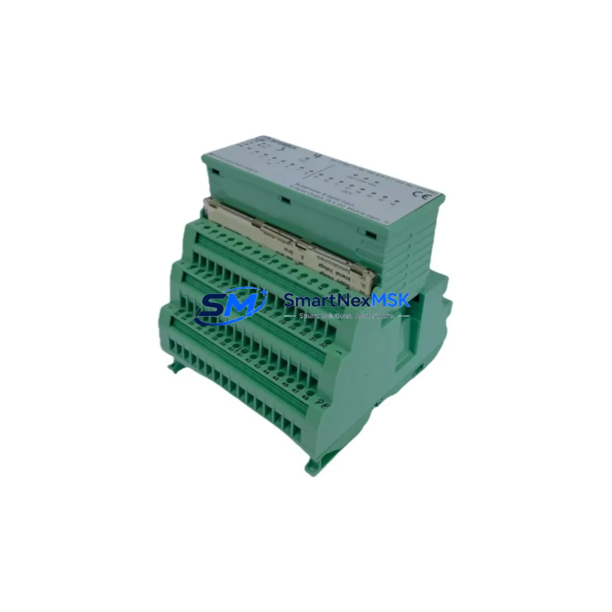
A successful retrofit of the 2866763 into an operational control cabinet requires a structured approach that accounts for the full power distribution chain. In most QUINT POWER installations, the PSU feeds a 24 VDC bus that simultaneously powers a Phoenix Contact AXL F BK ETH Axioline bus coupler, multiple AXL F DI8/1 DO8/1 digital I/O modules, and a QUINT-BUFFER/24DC/40 UPS buffer module. Each of these loads must be individually assessed against the 10 A output capacity of the 2866763 before the replacement is approved.
In control cabinets that also house a Phoenix Contact RFC 470S PN 3TX or ILC 151 ETH controller, the 24 VDC rail typically also supplies the CPU backplane and any installed QUINT-DIODE/40AC/2X20/1X40 redundancy modules. Engineers should use a clamp meter to log peak current draw during a full production cycle before sizing the replacement PSU. If peak loads approach 9.5 A, consider stepping up to the QUINT-PS/1AC/24DC/20 (Order No. 2866776) to maintain a 20% derating margin.
For systems that include Phoenix Contact FL SWITCH 2005 managed Ethernet switches or RAD-2400-IFS wireless I/O modules on the same 24 VDC rail, communication continuity during the PSU swap is critical. Where possible, use a QUINT-BUFFER/24DC/40 or an external 24 VDC UPS to bridge the 30–60 second power interruption during module exchange, preserving active PROFINET or Modbus TCP sessions and preventing controller warm-restart sequences that could trigger safety interlocks.
Terminal block compatibility is a frequent concern during QUINT POWER retrofits. The 2866763 uses the same 6.2 mm pitch terminal layout as earlier QUINT-PS generations, meaning existing Phoenix Contact ST 2.5 or UK 5 N feed-through terminals on the output bus do not require replacement. However, if the cabinet uses older screw-clamp terminals, this retrofit is an appropriate opportunity to upgrade to Push-in CAGE CLAMP technology for improved vibration resistance in high-cycle manufacturing environments.
Downtime Control During System Migration
Minimizing unplanned downtime is the primary operational constraint in any brownfield PSU replacement. For the 2866763 retrofit, the recommended procedure is to pre-configure and bench-test the replacement unit before the scheduled maintenance window. Set the output voltage trim to match the existing bus voltage (measured at the load terminals, not the PSU output), verify the DC OK signal contact wiring, and confirm that the inrush current profile does not trip the upstream MCB during a cold start.
During the physical swap, label all output wiring before disconnection and photograph the terminal layout. The 2866763’s Push-in terminals allow rapid re-termination without tools, reducing the hands-on panel time to under 15 minutes for a trained technician. After reconnection, power up the PSU in isolation (with load disconnected) to confirm output voltage stability before re-energizing the 24 VDC bus. This staged power-up sequence protects the RFC 470S PN 3TX controller and connected I/O modules from voltage transients during the initial energization.
Program logic preservation is non-negotiable. Before any power interruption, confirm that the PLC program is backed up to the Phoenix Contact SD card or to the engineering workstation via PC Worx or PLCnext Engineer. If the controller uses retain memory for process variables, verify that the retain data area is within the battery-backed SRAM capacity. For HMI panels connected via PROFINET — such as a Phoenix Contact TP 3057W or third-party Weintek/Siemens HMI — confirm that the HMI project references the correct controller IP address and that no IP lease renewals are triggered by the power cycle.
All units supplied by SMARTNEXMSK are pre-tested for output voltage accuracy, ripple, and DC OK signal function prior to dispatch. Each 2866763 ships with a 12-month warranty covering output regulation failure, terminal integrity, and manufacturing defects, giving maintenance teams confidence that the replacement unit will perform to specification from day one.
Retrofit Support FAQ
Q1: Is the 2866763 a direct drop-in replacement for earlier QUINT-PS/1AC/24DC/10 units?
Yes. The 2866763 shares the same DIN rail footprint, terminal pitch, output voltage range, and DC OK signal contact pinout as earlier QUINT-PS/1AC/24DC/10 production batches. No panel re-wiring or backplate modification is required for a like-for-like replacement. Verify the output voltage trim setting after installation, as factory default is 24.0 VDC.
Q2: What commissioning checks are required after installation?
After physical installation and wiring, perform the following: (1) measure output voltage at the bus terminals under no-load and full-load conditions; (2) confirm the DC OK relay contact closes within 2 seconds of power-up; (3) verify that the upstream MCB does not trip on inrush — if it does, check MCB curve type (Type B MCBs may trip; replace with Type C or D for QUINT-PS applications); (4) confirm PLC and I/O modules boot normally and that the HMI displays correct process values.
Q3: Can the 2866763 be used to replace a QUINT-PS/1AC/24DC/5 in an upgraded system?
Yes, with load assessment. The 2866763 provides 10 A output versus the 5 A of the QUINT-PS/1AC/24DC/5, making it suitable for panel upgrades where additional I/O modules, communication gateways, or field devices have been added to the 24 VDC bus. Confirm that the upstream AC wiring and MCB are rated for the higher input current draw of the 240 W unit.
Q4: What does the 12-month warranty cover, and how is it claimed?
The 12-month warranty covers manufacturing defects, output voltage regulation failure outside the specified ±1% tolerance, and terminal block integrity. To claim warranty, contact SMARTNEXMSK with the order number, a description of the fault, and measured output parameters. Units are replaced or repaired at no charge within the warranty period. Warranty does not cover damage caused by incorrect wiring, overvoltage on the AC input, or physical impact.
© 2026 SMARTNEXMSK. All rights reserved.
Original Source: https://smartnexmsk.com
Contact: sales@smartnexmsk.com | +86 18259474341