Phoenix Contact 2866789 QUINT-PS/1AC/24DC/40 Retrofit-Ready Power Supply for QUINT Series Control Systems
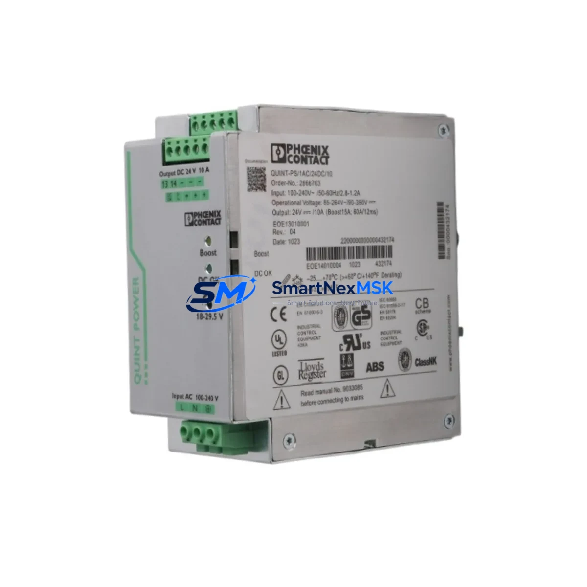
The Phoenix Contact 2866789 — model QUINT-PS/1AC/24DC/40 — is a high-performance 24VDC, 40A single-phase DIN rail power supply engineered for demanding industrial automation environments. With its robust design and wide input voltage tolerance (85–264VAC), this unit is a proven retrofit solution for aging QUINT-series power infrastructure in PLC control cabinets, distributed I/O panels, and process automation systems. Whether you are replacing a failed unit, upgrading an end-of-life power supply, or modernizing a legacy control system, the 2866789 delivers the output stability and protection features required for continuous industrial operation.
This power supply is fully compatible with standard 35mm DIN rail mounting and integrates seamlessly into existing QUINT-series panel layouts. Its SFB (Selective Fuse Breaking) technology enables reliable downstream circuit protection without nuisance tripping, making it particularly well-suited for systems with multiple parallel loads such as distributed I/O modules, communication gateways, and HMI panels.
Upgrade Compatibility Table
| Parameter | Details |
|---|---|
| Model / SKU | 2866789 / QUINT-PS/1AC/24DC/40 |
| Output Voltage | 24VDC (adjustable 18–29.5VDC) |
| Output Current | 40A continuous |
| Input Voltage | 85–264VAC, 1-phase, 47–63Hz |
| Mounting | 35mm DIN rail (EN 60715) |
| Terminal Compatibility | Standard screw terminals; compatible with Phoenix Contact CLIPLINE terminal blocks |
| Communication Interface | Signal contact (DC OK relay output) for PLC/SCADA integration |
| Replacement Compatibility | Direct retrofit for QUINT-PS/1AC/24DC/40 and functionally equivalent to earlier QUINT2 variants |
| Commissioning Notes | Verify output voltage trim, DC OK signal wiring, and downstream load sequencing before energizing |
| Warranty | 12 Months — covers manufacturing defects, output regulation failure, and protection circuit faults |
Retrofit Planning for Existing Automation Systems
When integrating the QUINT-PS/1AC/24DC/40 into an existing control system, a structured retrofit plan is essential to avoid unplanned downtime and configuration errors. Begin by auditing the total connected load in the control cabinet. Sum the current draw of all 24VDC consumers — including Phoenix Contact IB IL 24 DI 16 digital input modules, IB IL 24 DO 16 digital output modules, FL SWITCH 2005 managed Ethernet switches, and any HART or PROFIBUS communication modules — to confirm the 40A output capacity is sufficient with a minimum 20% headroom.
Next, inspect the existing terminal block layout. The QUINT-PS/1AC/24DC/40 uses standard screw-clamp terminals compatible with Phoenix Contact CLIPLINE PT series terminal blocks, which are commonly found in QUINT-era panels. If the legacy installation used an older QUINT-PS/1AC/24DC/20 or QUINT-PS/3AC/24DC/40 three-phase variant, verify that the AC input wiring gauge and circuit breaker rating match the new unit’s single-phase input requirements. A 25A Type C MCB on the AC input side is typically appropriate for the 40A output model.
For systems incorporating a Phoenix Contact AXL F BK PN PROFINET bus coupler or an ILC 150 ETH inline controller, confirm that the DC OK signal contact from the power supply is wired into the PLC’s digital input for power fault monitoring. This allows the control program to execute a controlled shutdown sequence rather than an abrupt loss of power, protecting both the process and the program memory of the controller.
If the retrofit involves migrating from a legacy Modbus RTU network to PROFINET or EtherNet/IP, the power supply changeover is an ideal opportunity to simultaneously upgrade the communication infrastructure. Install the new PSU alongside a Phoenix Contact FL COMSERVER UNI 232/422/485 serial-to-Ethernet gateway to bridge legacy serial devices during the transition period, maintaining production continuity while the new network backbone is commissioned.
For systems using Phoenix Contact RAD-900-IFS wireless I/O modules or remote I/O over radio, ensure the power supply’s output ripple specification (typically <50mV peak-to-peak) meets the sensitivity requirements of the wireless transceivers. The QUINT-PS/1AC/24DC/40’s active power factor correction and low output ripple make it well-suited for powering sensitive communication hardware.
Finally, document the DIN rail slot position, terminal assignments, and cable routing before removing the old unit. Photograph the existing wiring and label all conductors. This documentation will be critical during the post-installation verification and will significantly reduce commissioning time.
Downtime Control During System Migration
Minimizing production downtime during a power supply retrofit requires careful pre-staging and a disciplined switchover procedure. Before the maintenance window, pre-configure the replacement QUINT-PS/1AC/24DC/40 on a bench: set the output voltage trim to match the existing system’s nominal 24VDC level, test the DC OK relay contact continuity, and verify the unit powers up cleanly under a representative resistive load.
During the switchover, use a temporary 24VDC UPS or a second power supply in a parallel hot-standby configuration to maintain power to critical I/O modules and the PLC CPU — such as a Phoenix Contact ILC 131 ETH or ILC 350 PN controller — while the primary PSU is replaced. This approach keeps the PLC in RUN mode and preserves all retentive data and program logic without requiring a cold restart.
After installing the new unit, bring it online gradually: energize the AC input, confirm the DC OK signal is asserted, then transfer the load from the temporary supply. Monitor the output voltage under full load for a minimum of 10 minutes before declaring the retrofit complete. Check the HMI — whether a Phoenix Contact UNITY 7 or a third-party panel PC — for any power fault alarms that may have latched during the transition, and reset them as required.
Maintain the original program backup on a USB drive or the programming software (PC WORX or e!COCKPIT) before any power interruption. If the PLC uses battery-backed SRAM for retentive data, verify battery health before the maintenance window to prevent data loss during the brief power interruption.
Retrofit Support FAQ
Q1: Is the 2866789 QUINT-PS/1AC/24DC/40 a direct drop-in replacement for older QUINT models?
A: Yes. The 2866789 is dimensionally and electrically compatible with earlier QUINT-PS/1AC/24DC/40 variants. Terminal positions, DIN rail footprint, and DC OK signal wiring are consistent across the QUINT product generation. For systems originally fitted with a QUINT-PS/1AC/24DC/20, the 40A model provides additional current headroom for expanded I/O or additional communication modules added during the upgrade.
Q2: What wiring checks are required before commissioning?
A: Verify AC input conductor sizing (minimum 4mm² for 40A output), confirm PE (protective earth) bonding to the DIN rail, check that the DC output positive and negative busbars are correctly polarized, and test the DC OK relay contact wiring to the PLC input. Measure output voltage at the load terminals — not at the PSU output terminals — to account for cable voltage drop across long runs.
Q3: How is compatibility with existing PROFIBUS or PROFINET networks verified?
A: The power supply itself is network-agnostic; it provides clean 24VDC to all network components. Compatibility verification focuses on the powered devices: confirm that PROFIBUS DP slaves (e.g., Phoenix Contact IB IL 24 BK-PAC bus couplers) and PROFINET IO devices receive stable voltage within their specified operating range (typically 19.2–30VDC). Use a DC power quality meter to confirm output ripple is within specification before connecting sensitive communication hardware.
Q4: What does the 12-month warranty cover, and what is the claim process?
A: The 12-month warranty covers manufacturing defects, output voltage regulation failures, protection circuit malfunctions (SFB, OVP, OCP), and DC OK relay contact failures under normal operating conditions. To initiate a warranty claim, contact our sales team with the order reference, unit serial number, and a description of the fault. Units are tested prior to shipment; a pre-shipment test report is available upon request. Replacement units are dispatched within 3 business days of claim approval.
© 2026 SMARTNEXMSK. All rights reserved.
Original Source: https://smartnexmsk.com
Contact: sales@smartnexmsk.com | +86 18259474341