Phoenix Contact 2866802 Spare for QUINT-PS Automation: Spare Replacement & Industrial Downtime Risk Control
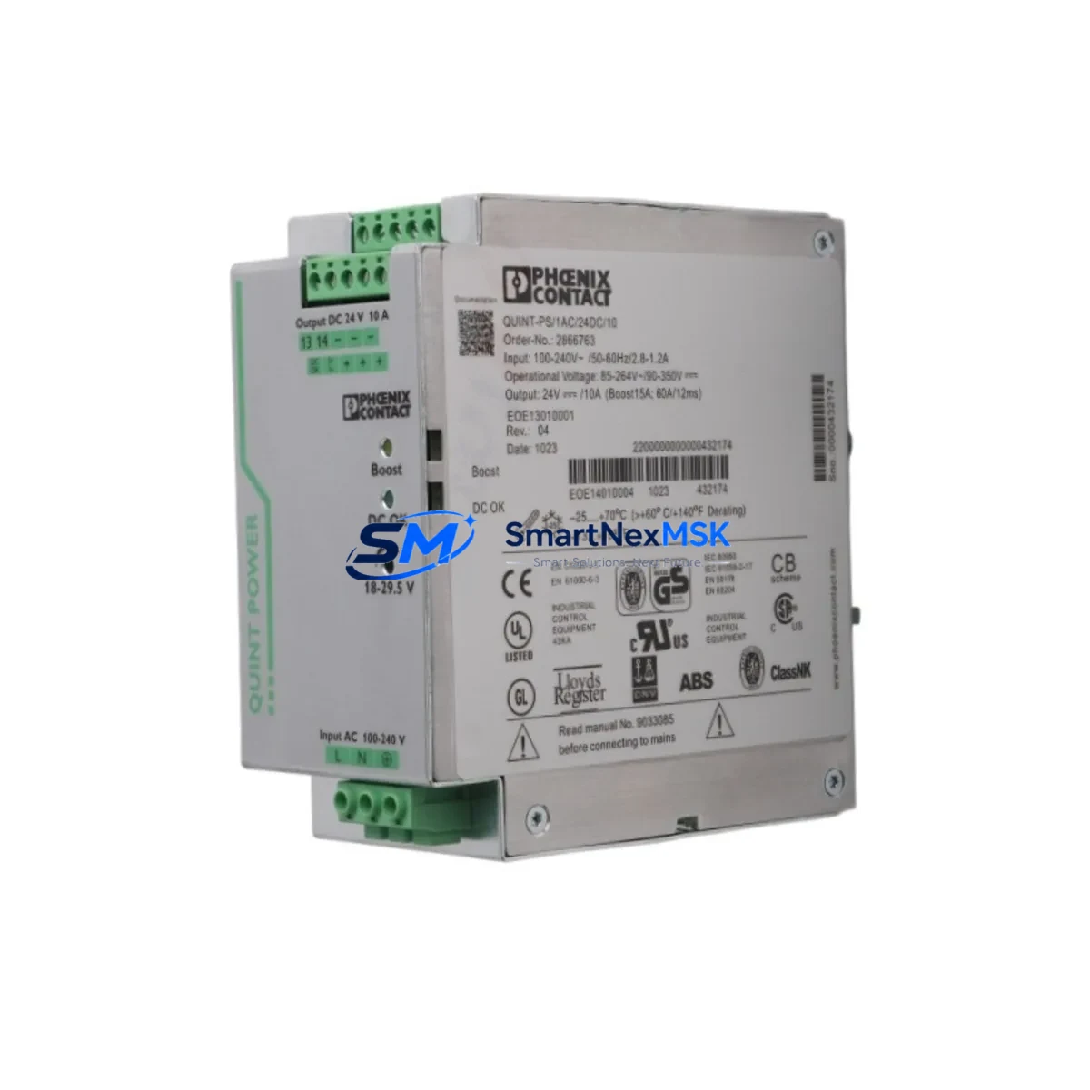
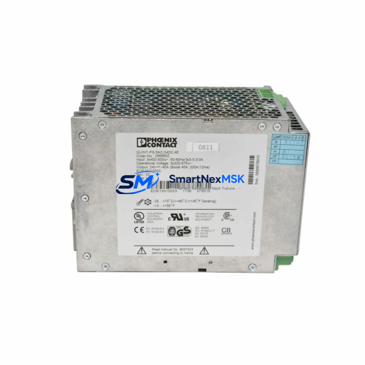
The Phoenix Contact 2866802 — model QUINT-PS/3AC/24DC/40 — is a three-phase DIN-rail mounted power supply delivering 24 VDC at 40 A continuous output. Designed for demanding industrial environments, this unit is a cornerstone component in control cabinets across manufacturing, process automation, and critical infrastructure. When this PSU fails or degrades, the downstream 24 VDC bus collapses, taking with it every PLC I/O module, relay output card, field sensor, and communication gateway that depends on it. Sourcing a verified, tested replacement unit is the fastest path to restoring system availability and minimizing unplanned downtime.
SMARTNEXMSK stocks the 2866802 as a maintenance-ready spare, pre-tested before dispatch, with a 12-month warranty covering electrical performance and output regulation. Each unit ships with full inspection documentation, making it suitable for direct installation in safety-critical and production-critical panels without additional incoming inspection delays.
Spare Maintenance Table
| Parameter | Specification |
|---|---|
| Part Number / SKU | 2866802 |
| Model | QUINT-PS/3AC/24DC/40 |
| Brand | Phoenix Contact |
| Series | QUINT-PS |
| Input Voltage | 3 AC 400/500 V (3-phase) |
| Output Voltage | 24 VDC (adjustable 18–29.5 V) |
| Output Current | 40 A continuous |
| Output Power | 960 W |
| Mounting | DIN rail (EN 60715 TH35) |
| Protection Class | IP20 |
| Operating Temperature | -25 °C to +70 °C |
| Approvals | UL, cUL, CE, GL, DNV |
| Country of Origin | Germany |
| Compatibility | Direct replacement for QUINT-PS/3AC/24DC/40; compatible with QUINT-BUFFER, QUINT-DIODE, and downstream 24 VDC bus loads |
| Installation | Snap onto TH35 DIN rail; connect 3-phase input L1/L2/L3/PE; verify output voltage before energizing load bus |
| Maintenance Recommendation | Inspect output voltage and ripple annually; check terminal torque; verify SFB (Static Boost) indicator status |
| Warranty | 12 Months — covers output regulation, switching performance, and electrical integrity |
Maintenance Planning for Continuous Operation
When a maintenance or procurement engineer schedules replacement of the 2866802, the power supply itself is rarely the only component that warrants attention. The QUINT-PS/3AC/24DC/40 sits at the top of the 24 VDC distribution hierarchy in the control cabinet, and its failure or degradation typically stresses adjacent components. A thorough site inspection during the replacement window should cover the following areas:
Upstream input protection: Verify the three-phase input fuses or circuit breaker feeding the PSU. Fuse holders and miniature circuit breakers (MCBs) rated for 3-phase 400/500 V input should be inspected for contact wear and correct trip rating. A blown or weakened fuse is often the root cause of PSU undervoltage trips rather than PSU failure itself.
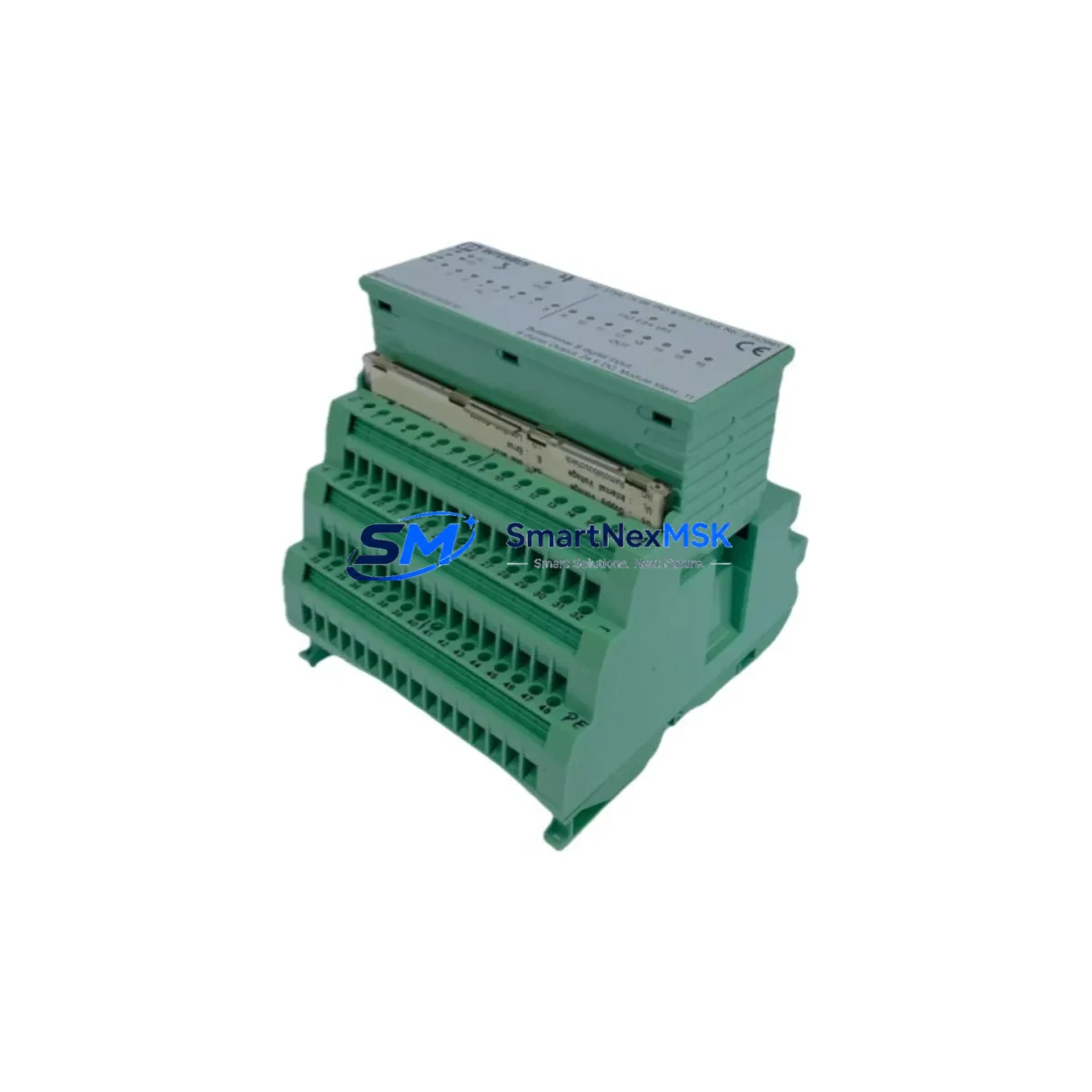
Output bus and load distribution: The 40 A output feeds a 24 VDC bus that typically supplies multiple PLC I/O modules — for example, Phoenix Contact Axioline F or Inline I/O modules — as well as relay output modules, solenoid valve drivers, and field transmitters. Each branch circuit should be protected by a Phoenix Contact PTFIX or similar DIN-rail terminal block fuse holder. Inspect fuse condition and terminal torque on all branch circuits before re-energizing.
Buffer and redundancy modules: If the installation includes a QUINT-BUFFER/24DC/40 or a QUINT-DIODE redundancy module, these units should be tested in parallel with the PSU replacement. Buffer capacitors degrade over time and may not provide the rated hold-up time even if the PSU itself is new.
PLC power and CPU modules: The 24 VDC bus directly powers the PLC backplane or CPU module. For Phoenix Contact RFC 470 or ILC 151 ETH controllers, verify that the CPU supply voltage is within tolerance after the new PSU is installed and the output voltage is trimmed. A marginal supply voltage can cause intermittent CPU resets that are difficult to diagnose after the fact.
Communication and gateway modules: Profibus DP couplers, PROFINET interface modules, and serial communication gateways (RS-485 repeaters, Modbus RTU converters) are sensitive to supply voltage transients during PSU switchover. After installation, monitor the communication bus for error frames or timeout alarms before returning the system to production.
Signal isolators and analog I/O: Signal isolators — such as Phoenix Contact MINI MCR or MACX MCR series — condition 4–20 mA and thermocouple signals and are powered from the same 24 VDC bus. Inspect isolator output accuracy after PSU replacement, as voltage sag during the previous PSU’s degradation period may have introduced calibration drift.
HMI and operator panels: Panel-mounted HMIs powered from the 24 VDC bus should be checked for display integrity and communication link status after the PSU is replaced. A brief power interruption during switchover can cause HMI configuration loss if the unit lacks internal battery backup.
Terminal blocks and wiring: Phoenix Contact PTFIX, UK, or MKDS series terminal blocks on the output side should be inspected for discoloration, loose ferrules, and correct torque. Thermal cycling from a degraded PSU can loosen terminal connections over time, creating resistance that causes localized heating even after the PSU is replaced.
Stocking the 2866802 as a critical spare — alongside a spare QUINT-BUFFER module, a set of branch fuses, and a spare CPU module — is the most effective strategy for reducing mean time to repair (MTTR) in facilities where this PSU architecture is widely deployed.
Site Replacement Workflow
Step 1 — Isolation and lockout: Isolate the three-phase input supply to the PSU using the upstream MCB or isolator switch. Apply LOTO (lockout/tagout) per site safety procedures. Verify absence of voltage on L1, L2, L3, and PE terminals using a calibrated multimeter.
Step 2 — Document existing configuration: Record the output voltage trim setting (visible on the front-panel potentiometer) and note the SFB indicator status before removal. Photograph terminal wiring if the cabinet drawing is not current.
Step 3 — Remove the failed unit: Loosen all input and output terminal screws. Disconnect wiring in sequence: output load bus first, then input phase conductors, then PE. Release the DIN-rail latch and slide the unit off the rail.
Step 4 — Install the 2866802 replacement: Snap the new unit onto the TH35 DIN rail. Reconnect PE first, then input phase conductors L1/L2/L3, then output load bus wiring. Torque all terminals to the manufacturer’s specification (typically 0.5–0.6 Nm for Phoenix Contact screw terminals).
Step 5 — Pre-energization checks: Verify input fuse continuity. Confirm output bus is not shorted. Set the output voltage trim to match the recorded setting from Step 2.
Step 6 — Energize and verify: Apply input power. Measure output voltage at the PSU terminals and at the far end of the 24 VDC bus. Verify SFB indicator is active (green). Confirm all downstream I/O modules, communication gateways, and HMI panels have resumed normal operation. Clear any PLC fault registers triggered by the power interruption.
Step 7 — Return to service and update records: Update the maintenance log with the replacement date, new unit serial number, and output voltage as-found/as-left values. Flag the 2866802 as a critical spare in the site spare parts inventory and initiate a replenishment order to restore stock level.
Spare Parts Support FAQ
Q1: Is the 2866802 a direct drop-in replacement for an existing QUINT-PS/3AC/24DC/40 installation?
Yes. The 2866802 is the Phoenix Contact part number for the QUINT-PS/3AC/24DC/40 and is a direct mechanical and electrical replacement. It uses the same TH35 DIN-rail footprint, identical terminal layout, and the same output voltage adjustment range. No wiring modifications or firmware changes are required for a like-for-like swap.
Q2: What pre-shipment testing does SMARTNEXMSK perform on the 2866802?
Each unit undergoes output voltage regulation testing at no-load and full-load conditions, input-to-output isolation verification, and SFB function confirmation before dispatch. Units that do not meet Phoenix Contact’s published specifications are quarantined and not shipped. A test report is available upon request for quality-critical applications.
Q3: What does the 12-month warranty cover, and how is a warranty claim handled?
The 12-month warranty covers defects in electrical performance, including output voltage regulation failure, SFB malfunction, and premature component failure under normal operating conditions. To initiate a claim, contact sales@smartnexmsk.com with the order number, unit serial number, and a description of the fault. SMARTNEXMSK will arrange return shipping and dispatch a replacement unit upon fault confirmation.
Q4: Can SMARTNEXMSK support long-term or blanket orders for the 2866802 as a site-critical spare?
Yes. For facilities operating multiple QUINT-PS/3AC/24DC/40 units, SMARTNEXMSK offers reserved stock arrangements and scheduled delivery programs to ensure spare availability without requiring large on-site inventory. Contact sales@smartnexmsk.com or call +86 18259474341 to discuss volume pricing and supply continuity agreements.
© 2026 SMARTNEXMSK. All rights reserved.
Original Source: https://smartnexmsk.com
Contact: sales@smartnexmsk.com | +86 18259474341