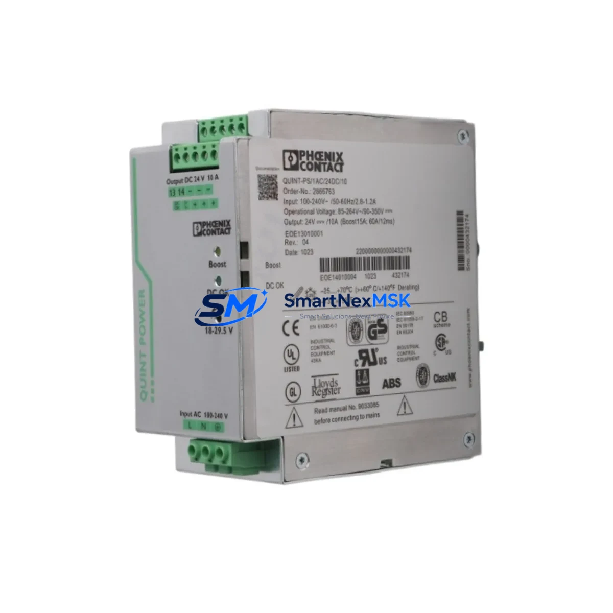
PHOENIX CONTACT QUINT-PS/1AC/24DC/10/CO 2320911: Retrofit-Ready Power Supply for Legacy Control Systems
The PHOENIX CONTACT QUINT-PS/1AC/24DC/10/CO (Part No. 2320911) is a 24 VDC, 10 A single-phase DIN rail power supply engineered for demanding industrial automation environments. With its QUINT POWER SFB (Selective Fuse Breaking) technology and integrated DC OK relay contact, this unit is a proven retrofit solution for aging control cabinets, legacy PLC racks, and distributed I/O panels that require a reliable, drop-in power upgrade without full system redesign.
Whether you are replacing an end-of-life QUINT-PS/1AC/24DC/5 or migrating from a third-party 24 VDC rail supply, the QUINT-PS/1AC/24DC/10/CO delivers the output headroom, diagnostic transparency, and DIN EN 60715 rail compatibility that system integrators and maintenance engineers depend on during brownfield modernization projects.
Upgrade Compatibility Table
| Parameter | QUINT-PS/1AC/24DC/10/CO 2320911 | Retrofit Notes |
|---|---|---|
| Input Voltage | 85–264 VAC / 90–350 VDC (wide range) | Compatible with single-phase 110 V and 230 V panels |
| Output Voltage | 24 VDC (adjustable 18–29.5 V) | Matches legacy 24 V bus; verify downstream device tolerances |
| Output Current | 10 A continuous (20 A SFB peak) | Replaces 5 A or 10 A predecessors; check total load budget |
| DIN Rail Mounting | DIN EN 60715 (35 mm) | Direct drop-in; no bracket modification required |
| DC OK Contact | Relay output (NC/NO) | Wire to PLC digital input for remote fault monitoring |
| Communication | None (standalone); pairs with QUINT-DIODE/40 for redundancy | Add QUINT-UPS/24DC/24DC/20 for battery backup integration |
| Replacement Path | QUINT-PS/1AC/24DC/5, QUINT-PS/1AC/24DC/10 (non-CO) | Terminal pitch identical; re-use existing wiring harness |
| Warranty | 12-Month Warranty — tested before shipment, certificate available on request | |
Retrofit Planning for Existing Automation Systems
Successful integration of the QUINT-PS/1AC/24DC/10/CO into a brownfield system begins with a thorough power budget audit. Before removing the legacy supply, document the total connected load across all 24 VDC consumers in the cabinet: SIMATIC S7-300 or S7-400 CPU modules, ET 200M or ET 200S distributed I/O racks, PROFIBUS DP repeaters, and any 24 VDC-powered SIEMENS SIMATIC HMI panels such as the TP700 Comfort or KTP900 Basic. Sum the rated currents and add a 20–30% derating margin to confirm the 10 A output is sufficient — or whether a parallel QUINT-PS/1AC/24DC/20 is warranted for high-density cabinets.
Terminal wiring is straightforward: the QUINT-PS/1AC/24DC/10/CO uses standard screw terminals accepting 0.2–10 mm² conductors. If the existing cabinet uses Phoenix Contact CLIPLINE complete terminal blocks such as the ST 2.5 or UK 6 series, the wiring harness can typically be re-used without re-ferrulling. Verify that the PE (protective earth) terminal is bonded to the cabinet rail and that the DC output negative is not floating if the downstream PLC backplane requires a grounded 0 V reference.
For systems incorporating a SIMATIC S7-300 with a PS 307 power supply module, the QUINT-PS/1AC/24DC/10/CO can serve as the 24 VDC logic supply while the PS 307 continues to power the backplane — a common split-rail architecture in retrofit projects where the original PS 307 5 A is undersized for expanded I/O. Similarly, when upgrading a MODICON Quantum or Premium PLC rack, the QUINT unit’s wide input range accommodates both 110 VAC and 230 VAC panel standards without jumper changes, simplifying cross-site standardization.
Communication protocol migration projects — for example, moving from PROFIBUS DP to PROFINET IO — often require adding new gateway modules such as the Anybus X-gateway or SIMATIC PN/DP coupler, which increases the 24 VDC load. The QUINT-PS/1AC/24DC/10/CO’s SFB technology ensures that a short-circuit on one branch does not collapse the entire 24 V bus, protecting the CPU and HMI from nuisance resets during commissioning of the new network segment. Pair it with a QUINT-DIODE/40 ORing diode module when building a redundant power architecture for high-availability lines.
All units are pre-tested under full load prior to shipment. Stock is maintained for immediate dispatch, and a 12-month warranty covers manufacturing defects from the date of invoice.
Downtime Control During System Migration
Minimizing unplanned downtime is the primary concern in any control system retrofit. The recommended approach is a staged hot-swap procedure: install the QUINT-PS/1AC/24DC/10/CO on a spare DIN rail section within the same cabinet while the legacy supply remains energized. Use a QUINT-UPS/24DC/24DC/20 uninterruptible power supply module as a bridge during the switchover window — this maintains 24 VDC to the PLC CPU, preserving the program in RAM and keeping the PROFIBUS or PROFINET network alive so that field devices such as Danfoss VLT drives, SMC pneumatic valve islands, and Turck TBEN I/O blocks do not lose their parameter sets.
Before cutting over, back up the PLC program from the CPU to a memory card or engineering station using SIMATIC Manager or TIA Portal. Verify that the HMI project on the TP700 Comfort or similar panel references the correct PLC IP address and that all alarm tags are mapped correctly — a power interruption that causes a CPU memory reset can corrupt the retentive data block if the backup battery in a SIMATIC S7-300 CPU 315-2 PN/DP is depleted. Replace the battery as part of the retrofit scope.
Once the QUINT-PS/1AC/24DC/10/CO is wired and the DC OK relay contact is connected to a spare DI channel on the ET 200S or S7-300 SM 321 digital input module, perform a load test at 80% of rated current before transferring the full cabinet load. This confirms output regulation and SFB response time before the line returns to production. Total switchover time for a well-prepared retrofit is typically under 30 minutes, keeping production impact within a single planned maintenance window.
Retrofit Support FAQ
Q1: Is the QUINT-PS/1AC/24DC/10/CO a direct replacement for the QUINT-PS/1AC/24DC/10 (without CO suffix)?
Yes. The CO suffix denotes the integrated DC OK relay contact output. The mechanical footprint, terminal layout, and output specifications are identical. The additional relay contact requires one pair of wires to the monitoring circuit; if not used, the terminals can be left open.
Q2: Can this unit replace a SIEMENS SITOP PSU100S 24V/10A in an existing cabinet?
Yes, with minor wiring adaptation. Both units mount on 35 mm DIN rail and share the same output voltage and current rating. Verify the input terminal torque specification and confirm the DC OK signal logic (the SITOP uses a transistor output; the QUINT uses a relay contact) before connecting to the PLC input module.
Q3: What commissioning checks are required after installation?
Measure output voltage at the terminal block under no-load and full-load conditions. Confirm the DC OK relay closes within 2 seconds of power-up. Test the SFB function by briefly short-circuiting a branch circuit through a 0.5 A fuse — the supply should recover automatically. Verify the PE bond resistance is below 0.1 Ω. Log all readings in the site commissioning record.
Q4: What does the 12-month warranty cover, and how is a claim processed?
The 12-month warranty covers manufacturing defects in materials and workmanship from the date of invoice. Each unit is tested under full load before shipment and a test certificate is available on request. To initiate a warranty claim, contact sales@smartnexmsk.com with the invoice number, unit serial number, and a description of the fault. Replacement or repair is arranged within 5 business days of fault confirmation.
© 2026 SMARTNEXMSK. All rights reserved.
Original Source: https://smartnexmsk.com
Contact: sales@smartnexmsk.com | +86 18259474341