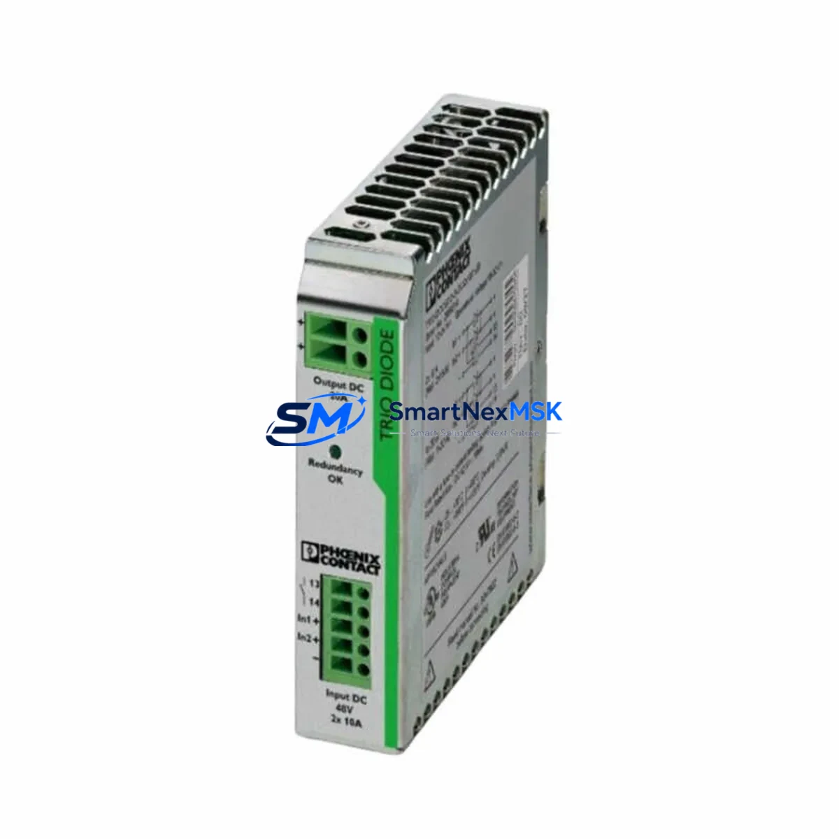
PHOENIX TRIO-DIODE/48DC/2X10/1X20 Retrofit-Ready Redundancy Module for TRIO Power Control Systems
The PHOENIX Contact TRIO-DIODE/48DC/2X10/1X20 is a high-reliability diode redundancy module engineered for 48 VDC industrial power systems requiring uninterrupted supply continuity. Rated at 2×10 A input channels and a combined 1×20 A output, this module is purpose-built for retrofit integration into existing TRIO Power series control cabinets, DIN-rail power distribution panels, and legacy automation architectures where a discontinued or aging redundancy component must be replaced without redesigning the entire power rail.
For system integrators and maintenance engineers managing aging control infrastructure, the TRIO-DIODE/48DC/2X10/1X20 represents a direct, drop-in replacement path. Its compact DIN-rail footprint and standardized terminal pitch align with the original TRIO Power mounting envelope, allowing technicians to swap the module during a scheduled maintenance window without modifying the cabinet backplane or rewiring the existing terminal block layout. The module’s passive diode-OR architecture ensures that if one PHOENIX Contact TRIO-POWER 48VDC supply — such as a TRIO-PS/1AC/48DC/10 or TRIO-PS/1AC/48DC/5 — experiences a fault, the second supply immediately assumes full load without any control signal intervention, protecting downstream PLCs, remote I/O nodes, and field instruments from power interruption.
Upgrade Compatibility Table
| Parameter | TRIO-DIODE/48DC/2X10/1X20 | Retrofit Notes |
|---|---|---|
| Input Voltage | 48 VDC | Verify upstream TRIO-PS supply is rated 48 VDC; do not substitute 24 VDC variants |
| Input Channels | 2 × 10 A | Each channel connects to one redundant PSU; confirm cable cross-section ≥ 1.5 mm² |
| Output Current | 1 × 20 A max | Derate to 18 A at 50 °C ambient; check total downstream load before commissioning |
| Mounting | 35 mm DIN rail (EN 60715) | Direct replacement for prior TRIO-DIODE generations; no rail modification required |
| Terminal Connection | Screw terminals, 0.2–6 mm² | Re-use existing ferrule-terminated conductors; torque to 0.5–0.6 N·m |
| Communication Interface | None (passive diode-OR) | No fieldbus or protocol configuration required; transparent to PLC logic |
| Replacement Compatibility | TRIO-DIODE/48DC/2X10/1X20 (all prior revisions) | Confirm revision suffix on nameplate; functional equivalence verified |
| Commissioning Check | Load test at 100% rated current | Simulate single-PSU fault; verify output voltage remains within ±1% of nominal |
| Warranty | 12 Months | Covers manufacturing defects; includes pre-shipment functional test report |
Retrofit Planning for Existing Automation Systems
Successful integration of the TRIO-DIODE/48DC/2X10/1X20 into a brownfield control system begins with a thorough power audit. Before removing the failed or obsolete redundancy module, engineers should document the total connected load on the 48 VDC bus — including all active field devices, 24 VDC converters fed from the 48 V rail, and any PHOENIX Contact QUINT-PS or MINI-PS auxiliary supplies sharing the same distribution bar. This baseline load figure determines whether the replacement module’s 20 A output rating provides adequate headroom or whether a parallel redundancy topology using two TRIO-DIODE units is warranted.
Terminal wiring is the most time-sensitive step during a live-system retrofit. The TRIO-DIODE/48DC/2X10/1X20 uses the same screw-terminal pitch as its predecessors, so existing cable harnesses — typically terminated with DIN 46228 ferrules — can be transferred directly. Technicians should label each conductor before disconnection and photograph the original wiring arrangement. Input channel 1 connects to the primary TRIO-PS supply, and input channel 2 connects to the standby unit; reversing these connections does not affect diode-OR function but may confuse future maintenance personnel reviewing the as-built drawings.
For control cabinets that also house a PHOENIX Contact ILC 150 ETH or AXC F 2152 controller communicating over PROFINET or Modbus TCP, the power redundancy module swap is entirely transparent to the PLC program. No address reassignment, no I/O mapping changes, and no HMI screen updates are required — the TRIO-DIODE operates below the fieldbus layer. However, if the cabinet includes a PHOENIX Contact FL SWITCH 2008 managed Ethernet switch or a RAD-ISM-900 wireless gateway drawing from the same 48 V bus, engineers should verify that the switch’s PoE budget and the gateway’s inrush current do not momentarily exceed the module’s 20 A output during a cold-start sequence.
Where the retrofit involves migrating from an older 24 VDC redundancy architecture to a 48 VDC system — a common upgrade path driven by longer cable runs and reduced conductor cross-section requirements — the TRIO-DIODE/48DC/2X10/1X20 pairs naturally with a PHOENIX Contact STEP-PS/1AC/24DC/48DC/3 DC-DC converter to bridge legacy 24 V field devices. This approach preserves existing sensor wiring while modernizing the backbone power distribution, reducing copper costs and voltage-drop losses across the panel.
Backplane and rack considerations are minimal for this module: the TRIO-DIODE mounts independently on a standard 35 mm DIN rail and does not require a dedicated backplane connector or system bus slot. This makes it equally suitable for standalone power panels, distributed control cabinets, and MCC (Motor Control Center) auxiliary power sections. Engineers retrofitting PHOENIX Contact Inline or Axioline remote I/O stations — such as IB IL 24 DI 16 digital input modules or IB IL 24 DO 16 digital output modules — will find that the TRIO-DIODE’s passive architecture introduces no additional latency or protocol overhead into the I/O scan cycle.
Downtime Control During System Migration
Minimizing unplanned downtime is the primary constraint in any brownfield power system retrofit. The recommended approach for replacing a TRIO-DIODE/48DC/2X10/1X20 in a live production environment is a hot-standby swap sequence: first, confirm that the standby PSU is carrying zero load by measuring the diode module’s output voltage with both inputs energized. Then de-energize only the primary input channel, transfer the terminal connections to the new module, re-energize, and verify output voltage stability before switching the standby channel. This sequence keeps the downstream 48 VDC bus live throughout the procedure, protecting active PLC scan cycles, ongoing PROFINET communication frames, and any safety relay logic that monitors bus voltage.
For systems where a brief interruption is unavoidable — such as when the entire power section must be isolated for cabinet rewiring — engineers should export the current PLC program from the PHOENIX Contact PC WORX or PLCnext Engineer environment before beginning work, store it on a USB drive or network share, and prepare a restoration checklist that includes: re-establishing Modbus TCP node addresses, verifying PROFINET device names, confirming analog input scaling on any PHOENIX Contact MCR signal conditioners, and re-enabling any watchdog timers that may have tripped during the power interruption. HMI screens connected via OPC-UA or Modbus should be tested in simulation mode before returning the system to automatic control.
Pre-shipment functional testing of each TRIO-DIODE/48DC/2X10/1X20 unit — conducted at rated load with a simulated single-channel fault — ensures that field commissioning time is limited to wiring verification and a brief load test rather than component-level troubleshooting. All units supplied by SMARTNEXMSK are tested prior to dispatch, and a 12-month warranty covers any manufacturing defects identified during the warranty period. Stocking a spare TRIO-DIODE unit alongside the primary installation is strongly recommended for critical 48 VDC infrastructure where mean time to repair (MTTR) targets are below four hours.
Retrofit Support FAQ
Q1: Is the TRIO-DIODE/48DC/2X10/1X20 a direct replacement for all previous revisions of the same part number?
A: Yes. PHOENIX Contact has maintained functional and dimensional compatibility across all production revisions of this part number. The terminal layout, DIN-rail clip position, and electrical ratings are identical. Confirm the nameplate voltage (48 VDC) and current rating (2×10 A / 1×20 A) match your application before installation.
Q2: Do I need to reconfigure my PLC or update my HMI after replacing this module?
A: No. The TRIO-DIODE/48DC/2X10/1X20 is a passive diode-OR device with no fieldbus interface, no device address, and no software configuration. Your PLC program, PROFINET topology, Modbus register map, and HMI tag database remain unchanged. The only post-installation step is a functional load test to confirm output voltage is within specification.
Q3: What wiring checks should I perform before energizing the replacement module?
A: Verify conductor cross-section (minimum 1.5 mm² for 10 A channels), confirm ferrule crimping is secure, check that input channel polarity matches the upstream PSU output polarity, and measure insulation resistance between input channels and chassis ground. Torque all screw terminals to 0.5–0.6 N·m and perform a continuity check on the output bus bar before applying load.
Q4: What does the 12-month warranty cover, and how is a warranty claim processed?
A: The 12-month warranty covers manufacturing defects in materials and workmanship from the date of shipment. Each unit is functionally tested at rated load prior to dispatch. To initiate a warranty claim, contact SMARTNEXMSK with the order number, a description of the fault symptom, and photographs of the installation. Replacement units are dispatched within 3 business days of fault confirmation.
© 2026 SMARTNEXMSK. All rights reserved.
Original Source: https://smartnexmsk.com
Contact: sales@smartnexmsk.com | +86 18259474341