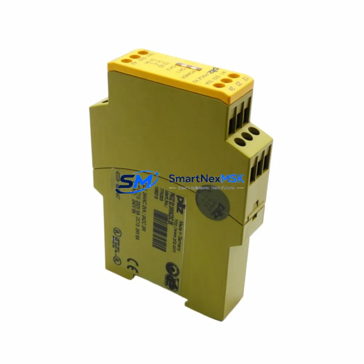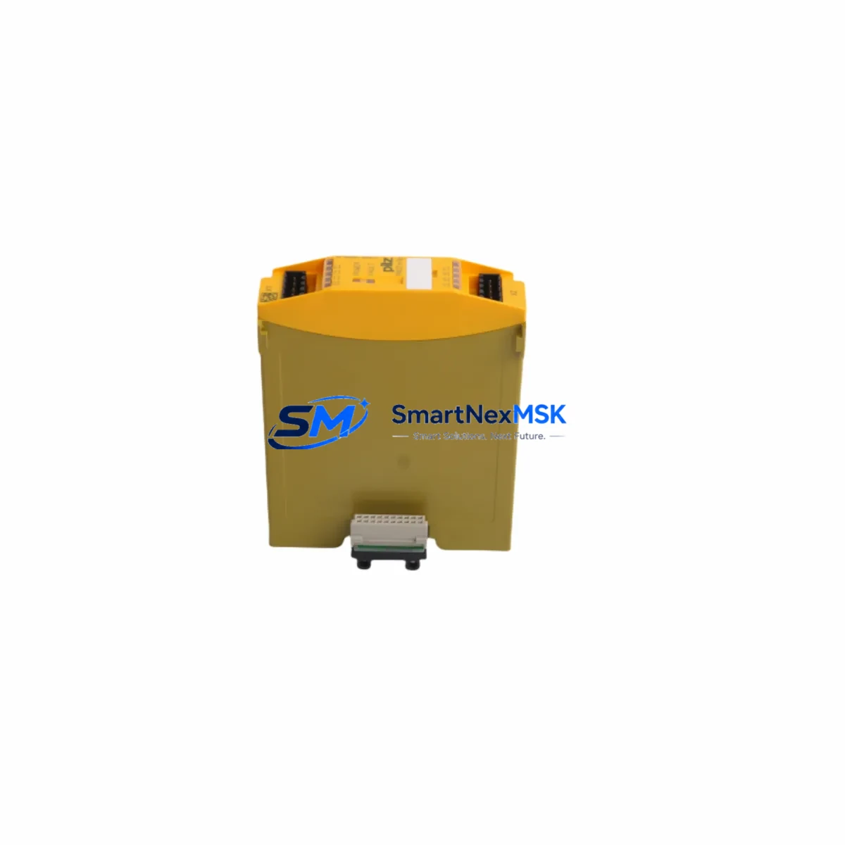
PILZ 773400 PNOZ mi1p Retrofit-Ready Safety Input Module for PNOZ m Control Systems
The PILZ 773400 PNOZ mi1p is an 8-channel safe input expansion module engineered for seamless integration into the PNOZ m modular safety relay platform. Certified to SIL 3 (IEC 62061) and PLe / Category 4 (EN ISO 13849-1), this module is the preferred retrofit solution for facilities migrating away from legacy hardwired relay circuits or earlier-generation PNOZ Classic units. Whether you are upgrading a standalone machine guard, modernizing a press-brake safety circuit, or expanding an existing PNOZ m B0 base unit, the 773400 delivers the diagnostic coverage and channel density required for high-demand safety applications.
Upgrade Compatibility Table
| Parameter | PILZ 773400 PNOZ mi1p | Retrofit Notes |
|---|---|---|
| Safe Input Channels | 8 × safe digital inputs | Replaces up to 4 dual-channel PNOZ X relay circuits |
| Safety Integrity Level | SIL 3 / PLe Cat. 4 | Meets or exceeds most legacy relay-based SIL 2 installations |
| Supply Voltage | 24 V DC (via PNOZ m B0 base unit) | Confirm base unit PSU capacity before adding expansion modules |
| Backplane Interface | PNOZ m system bus connector | Compatible with PNOZ m B0 (773100) and PNOZ m B1 (773101) base units |
| Module Address | Auto-assigned by base unit slot position | Verify slot assignment in PNOZmulti Configurator software after installation |
| Communication Protocol | Internal PNOZ m system bus (proprietary) | No fieldbus adapter required; optional PROFINET / EtherNet/IP via PNOZ m gateway modules |
| Programming Tool | PNOZmulti Configurator (v10.x or later) | Existing project files can be extended; no full reprogram required for module addition |
| Terminal Wiring | Spring-clamp terminals, 0.2–2.5 mm² | Re-use existing 1.5 mm² cable runs; verify terminal labeling against new wiring diagram |
| HMI / SCADA Integration | Status bits readable via gateway to PLC | Update HMI faceplates to reflect expanded I/O point list |
| Commissioning Test | Functional test required per IEC 62061 §8 | Perform proof-test on all 8 input channels before live restart |
| Warranty | 12-Month Warranty — covers manufacturing defects; includes pre-shipment functional verification | |
Retrofit Planning for Existing Automation Systems
Integrating the PILZ 773400 PNOZ mi1p into an existing control cabinet begins with a thorough audit of the current safety architecture. In most retrofit scenarios, the base unit is a PNOZ m B0 (773100) or PNOZ m B1 (773101), and the 773400 is added as an expansion to increase the number of monitored safety inputs — for example, when a machine line is extended with additional light curtains, two-hand control stations, or emergency-stop buttons.
Before mounting the module, verify that the 24 V DC power supply feeding the base unit has sufficient residual capacity. Each PNOZ mi1p draws current from the system bus; adding multiple expansion modules — such as a PNOZ mo4p (773600) output expansion alongside the mi1p — can push total consumption close to the base unit’s rated bus current. A PNOZ m ES (773830) power supply expansion unit may be required in larger configurations.
Terminal wiring on the 773400 follows the same spring-clamp convention used across the PNOZ m family. Existing cable runs from safety sensors can typically be re-terminated directly, but engineers should cross-reference the new wiring diagram generated by PNOZmulti Configurator against the legacy schematic. Pay particular attention to input channel pairing: dual-channel inputs (e.g., from a safety door switch with two NC contacts) must be assigned to complementary channel pairs within the module to achieve Cat. 4 / PLe diagnostics.
If the existing system communicates safety status to a supervisory PLC — for example, a Siemens S7-300 or S7-1500 via PROFIBUS or PROFINET — a PNOZ m EF ProfisafeGW (773900) or equivalent gateway module must be present on the PNOZ m rack. The gateway maps PNOZ m I/O data, including the new mi1p channels, into the PLC’s F-CPU process image. After adding the 773400, the PLC safety program (written in STEP 7 Safety or TIA Portal Safety) must be updated to include the new input signals, and a full safety validation cycle — including a SISTEMA recalculation — is recommended.
For facilities running older PNOZ X series relays (e.g., PNOZ X3, PNOZ X5, PNOZ XV2) that are being phased out due to end-of-life or spare-parts scarcity, the PNOZ m platform with the 773400 mi1p provides a compact, software-configurable replacement. A single PNOZ m B0 base unit with one or two mi1p expansion modules can consolidate the functions of four to eight discrete PNOZ X relays, dramatically reducing cabinet footprint and wiring complexity. Replacement of PNOZ X relay bases and associated PNOZ X terminal blocks with the PNOZ m rail-mount assembly is straightforward and typically completed within a planned maintenance window.
Where HMI visualization is involved — for instance, a PILZ PMI v10 HMI or a third-party panel running WinCC or FactoryTalk — the safety status bits exposed via the gateway must be mapped to updated HMI faceplates. This step is often overlooked during rapid retrofits and can cause operator confusion if legacy alarm tags reference input addresses that have shifted due to the new module slot assignment.
Downtime Control During System Migration
Minimizing unplanned downtime is the primary concern for any safety system retrofit. The recommended approach for integrating the PILZ 773400 PNOZ mi1p is to complete all pre-work — PNOZmulti Configurator project modification, updated wiring diagrams, cable pre-fabrication, and HMI faceplate revision — before the scheduled maintenance window begins.
During the window itself, the sequence is: (1) de-energize and lock out the control cabinet; (2) mount the 773400 in the next available slot on the PNOZ m rack; (3) re-terminate input cables per the new wiring diagram; (4) download the updated PNOZmulti project to the base unit via the USB programming interface; (5) restore power and verify that the base unit recognizes the new module (green LED on mi1p); (6) perform a channel-by-channel functional test by actuating each connected safety device and confirming the corresponding input bit in PNOZmulti Configurator’s online diagnostic view; (7) update and validate the PLC safety program if a gateway is present; (8) obtain sign-off from the responsible safety engineer before returning the machine to production.
Because the PNOZ m platform stores its configuration in the base unit’s non-volatile memory, the original program logic for all previously installed modules — including any PNOZ mo4p output modules or PNOZ mi2p (773401) analog input modules — is preserved during the addition of the new mi1p. There is no need to re-enter existing logic, which significantly reduces the risk of introducing errors during the migration and keeps the maintenance window as short as possible.
For critical production lines where even a brief outage is costly, consider staging the retrofit on a duplicate cabinet or test bench using a spare PNOZ m B0 (773100) base unit. This allows full functional verification of the new configuration — including gateway communication to the F-CPU and HMI status display — before the live system is touched.
Retrofit Support FAQ
Q1: Is the PILZ 773400 PNOZ mi1p a direct drop-in replacement for PNOZ X series relays?
Not a pin-for-pin replacement, but a functional equivalent. The PNOZ mi1p operates as part of the PNOZ m modular platform rather than as a standalone relay. Migration requires a PNOZ m B0 or B1 base unit and a PNOZmulti Configurator project. The functional result — monitored dual-channel safety inputs with SIL 3 / PLe certification — is equivalent or superior to the legacy PNOZ X units being replaced. We supply the 773400 pre-tested and ready for installation.
Q2: What wiring changes are needed when retrofitting from PNOZ X3 or PNOZ X5 units?
Input cables from safety devices (E-stops, light curtains, door switches) can generally be re-used. The key change is re-terminating from the PNOZ X relay’s screw terminals to the PNOZ mi1p’s spring-clamp terminals, and re-pairing channels according to the new wiring diagram from PNOZmulti Configurator. Output relay wiring from the old PNOZ X units must be re-routed to a PNOZ mo4p (773600) or similar output expansion module on the PNOZ m rack.
Q3: Can I add the 773400 to an existing PNOZ m system without reprogramming the entire project?
Yes. In PNOZmulti Configurator, you add the mi1p to the existing rack layout, assign the new input channels to the required safety functions, and download only the updated project. Existing logic blocks for previously installed modules remain unchanged. A functional test of the new channels is required before restart, but the overall reprogram time is minimal.
Q4: What does the 12-month warranty cover, and is pre-shipment testing performed?
Every PILZ 773400 PNOZ mi1p shipped by SMARTNEXMSK undergoes pre-shipment functional verification to confirm module recognition, input channel response, and LED status indication. The 12-month warranty covers manufacturing defects and module failure under normal operating conditions. Units are shipped with original PILZ packaging and documentation where available. For warranty claims or technical commissioning support, contact sales@smartnexmsk.com.
© 2026 SMARTNEXMSK. All rights reserved.
Original Source: https://smartnexmsk.com
Contact: sales@smartnexmsk.com | +86 18259474341