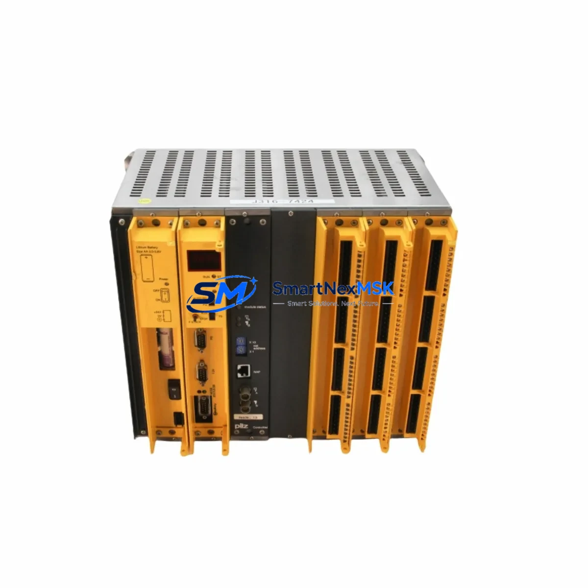
Pilz PSS1 BMP 5/2GRUNDTRAGER 839-034095-001 Retrofit Base Rack: Compatible Modernization for PSS1 Control Systems
The Pilz PSS1 BMP 5/2GRUNDTRAGER (Part No. 839-034095-001 / 839-034098-001) is a 5-slot safety PLC base rack designed for the Pilz PSS1 programmable safety system platform. As PSS1-series hardware reaches end-of-life and spare parts become increasingly scarce, this retrofit-ready base rack provides a verified replacement path for facilities operating legacy safety control cabinets, machine guarding systems, and process interlocks built around the PSS1 architecture.
Whether you are managing a planned upgrade cycle, responding to an unplanned module failure, or executing a broader control system modernization project, the BMP 5/2GRUNDTRAGER serves as the structural and electrical backbone of your PSS1 rack assembly. It accepts PSS1-series I/O modules, communication modules, and the PSS1 CPU module, preserving your existing program logic and field wiring topology during the transition.
Upgrade Compatibility Table
| Parameter | Specification / Recommendation |
|---|---|
| Part Numbers | 839-034095-001 / 839-034098-001 |
| Platform Compatibility | Pilz PSS1 Series Safety PLC |
| Slot Configuration | 5-slot base rack (BMP 5/2) |
| Backplane Interface | PSS1 proprietary backplane bus; compatible with PSS1 CPU, I/O, and communication modules |
| Installation Requirement | DIN rail or panel mount; verify cabinet depth and rail spacing before installation |
| Power Supply Compatibility | Requires PSS1-compatible 24 VDC power supply module (e.g., PSS SB 006 or equivalent) |
| Communication Compatibility | Supports PSS1 PROFIBUS-DP, DeviceNet, and serial communication modules installed in rack slots |
| Replacement Recommendation | Direct drop-in replacement for existing BMP 5/2GRUNDTRAGER installations; no rack rewiring required |
| Commissioning Notes | Verify module slot addressing, CPU firmware version, and I/O channel mapping after rack swap |
| Warranty | 12-Month Warranty — covers manufacturing defects and functional failures under normal operating conditions |
Retrofit Planning for Existing Automation Systems
Replacing a PSS1 base rack in a live production environment requires careful pre-planning across multiple system layers. Before removing the existing BMP 5/2GRUNDTRAGER, engineers should document the physical slot positions of all installed modules — including the PSS1 CPU module, any PSS1 digital input/output modules (such as the PSS DIO 16/16 or PSS AI 4/AO 2), and any installed communication interface modules such as the PSS PROFIBUS DP slave module. Slot addressing in the PSS1 system is position-dependent, and incorrect reinstallation will cause configuration mismatches that prevent the CPU from recognizing field devices.
Power budget verification is a critical pre-installation step. The PSS1 backplane distributes 24 VDC logic power across all installed modules through the rack’s internal bus. Before installing the replacement BMP 5/2GRUNDTRAGER, calculate the total current draw of all modules to be installed and confirm that the existing PSS SB power supply module — or its replacement — can sustain the load with adequate margin. Overloading the backplane bus is a common cause of intermittent faults in retrofitted PSS1 systems.
Terminal wiring on PSS1 I/O modules is handled at the module level rather than at the rack, which simplifies the physical swap of the base rack itself. However, if the retrofit also involves replacing aging PSS1 digital input modules or analog I/O modules, technicians must re-verify field wiring polarity, signal ranges, and terminal torque specifications. Any changes to I/O channel assignments must be reflected in the PSS WIN software project before the system is restarted.
For facilities migrating from PSS1 to the newer Pilz PSSuniversal or PSS 4000 platform, the BMP 5/2GRUNDTRAGER serves as an interim solution that maintains operational continuity while the migration project is staged across multiple shutdowns. In this scenario, the existing PSS1 CPU program — developed in PSS WIN — can continue to run on the original hardware while new PSSuniversal multi-function modules or PSS 4000 I/O modules are commissioned in parallel on a separate rack. Communication between legacy PSS1 nodes and new platform nodes is typically bridged via PROFIBUS-DP, using the PSS1 PROFIBUS DP master module on the existing rack and a corresponding slave interface on the new system.
HMI integration should also be reviewed during the retrofit. If the existing control cabinet includes a Pilz PVIS or third-party HMI panel communicating with the PSS1 CPU via serial RS-232 or PROFIBUS, the communication link must be re-established and tested after the rack swap. Screen variable mappings, alarm tag addresses, and data block references in the HMI project may require updates if any module slot positions change during the retrofit.
Programming cables — such as the PSS WIN programming cable used to connect a laptop to the PSS1 CPU’s programming port — should be on-site during commissioning. After the rack replacement, a full online comparison between the running CPU program and the archived PSS WIN project file is recommended to confirm program integrity before returning the machine to production.
Downtime Control During System Migration
Minimizing unplanned downtime during a PSS1 rack replacement begins with preparation, not execution. The single most effective downtime-reduction measure is to pre-stage the replacement BMP 5/2GRUNDTRAGER with all required modules installed and addressed before the maintenance window begins. This means pre-installing the PSS1 CPU module, I/O modules, and any communication modules into the new rack, verifying slot positions against the original configuration drawing, and performing a bench-level power-on test using a portable 24 VDC supply before the rack enters the cabinet.
Program backup is non-negotiable. Before any hardware is disturbed, the current PSS1 CPU program must be uploaded from the running controller and saved to a secure location using PSS WIN software. This backup protects against data loss in the event that the CPU module is damaged during handling or that the replacement rack exhibits unexpected behavior during initial power-up.
For systems where continuous safety monitoring cannot be interrupted — such as press guarding, robot cell interlocks, or conveyor safety zones — a temporary bypass procedure approved by the site safety officer may be required during the rack swap interval. All bypass activities must be documented, time-limited, and reversed immediately upon successful commissioning of the replacement rack.
After the new BMP 5/2GRUNDTRAGER is installed and powered, the recommended commissioning sequence is: (1) verify CPU status LEDs indicate normal operation, (2) confirm all I/O module status LEDs are green, (3) perform an online program comparison in PSS WIN, (4) test all safety input channels using the field device (e-stop, light curtain, safety gate) before re-enabling machine motion, and (5) document the completed retrofit in the machine’s maintenance log. This structured approach consistently reduces total rack replacement time to under four hours for experienced PSS1 technicians.
Retrofit Support FAQ
Q: Is the 839-034098-001 a direct substitute for the 839-034095-001?
A: Yes. Both part numbers refer to the PSS1 BMP 5/2GRUNDTRAGER base rack. The suffix difference reflects a minor revision or regional packaging variant. Both are electrically and mechanically interchangeable in PSS1 rack assemblies. We supply whichever variant is available from verified stock and confirm compatibility before shipment.
Q: Can I reuse my existing PSS1 CPU and I/O modules in the replacement rack?
A: Yes, provided the existing modules are in serviceable condition. The BMP 5/2GRUNDTRAGER replacement rack accepts all standard PSS1-series modules without modification. After reinstalling modules into the new rack, perform a full online program comparison in PSS WIN and test all I/O channels before resuming production.
Q: What does the 12-month warranty cover?
A: The 12-month warranty covers manufacturing defects and functional failures under normal operating conditions from the date of shipment. It does not cover damage resulting from incorrect installation, overvoltage, or physical impact. Warranty claims are processed within 5 business days of receiving the returned unit, with replacement or repair at our discretion.
Q: Do you provide pre-shipment testing for the BMP 5/2GRUNDTRAGER?
A: Yes. All units undergo functional verification prior to shipment, including backplane bus continuity checks and visual inspection for connector damage. A test report is available upon request. Units are shipped in anti-static packaging with foam protection to prevent transit damage.
© 2026 SMARTNEXMSK. All rights reserved.
Original Source: https://smartnexmsk.com
Contact: sales@smartnexmsk.com | +86 18259474341