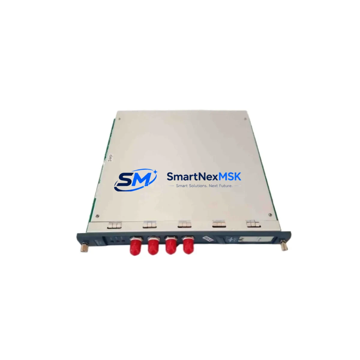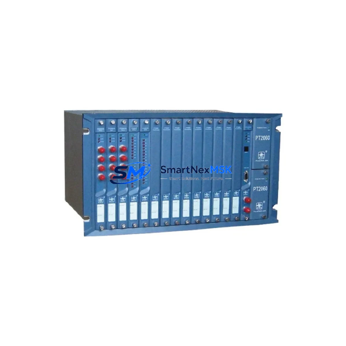
ProvibTech PT2060/53 Maintenance-Ready Spare PT2060 Series
When a vibration monitor module fails in a rotating machinery protection system, every minute of unplanned downtime translates directly into production loss and safety risk. The ProvibTech PT2060/53 is a factory-original spare module designed for the PT2060 series machinery protection system — a platform widely deployed in turbines, compressors, pumps, fans, and other critical rotating assets across power generation, petrochemical, and heavy manufacturing facilities.
Sourced as an original ProvibTech component, the PT2060/53 is pre-tested prior to dispatch and supplied with a 12-month warranty. It is stocked specifically to support maintenance engineers and procurement teams who need a verified, drop-in replacement that restores system integrity without requiring reconfiguration or recalibration of the wider protection rack.
Whether you are executing a planned shutdown, responding to a channel fault alarm, or building a strategic spare parts inventory for a long-running PT2060 installation, the PT2060/53 is the correct module to specify. Our team supports compatibility verification, pre-shipment functional testing, and long-term supply continuity for legacy ProvibTech systems.
Spare Maintenance Table
| Parameter | Specification / Detail |
|---|---|
| Part Number / SKU | PT2060/53 |
| Brand | ProvibTech |
| Series | PT2060 Machinery Protection System |
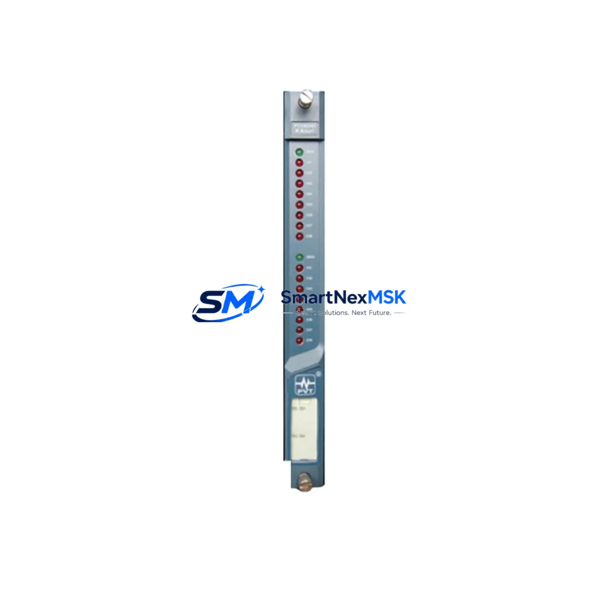
| Module Function | Vibration Monitor Module — signal conditioning, measurement, and relay output for rotating machinery protection |
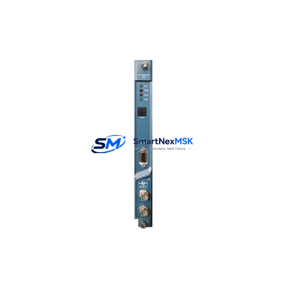
| Compatibility | PT2060 series rack; compatible with ProvibTech PT2060/01 power supply, PT2060/02 backplane, and PT2060-series I/O and relay modules |
| Input Signal Type | Eddy-current / proximity probe signal (Bently Nevada-compatible interface, industry standard) |
| Output | 4–20 mA analog output; relay contact outputs for alert and danger thresholds |
| Measurement Parameters | Radial vibration (displacement, velocity); configurable alert/danger setpoints |
| Operating Voltage | 24 VDC (supplied via PT2060 backplane) |
| Operating Temperature | 0°C to +60°C (standard industrial control cabinet environment) |
| Mounting | DIN-rail / rack-mount into PT2060 chassis; plug-in module format |
| Origin | China (ProvibTech manufacturing) |
| Weight | Approx. 1,040 g (packaged) |
| Warranty | 12 Months — covers manufacturing defects; pre-shipment functional test included |
| Maintenance Recommendation | Inspect annually during planned shutdown; replace on channel fault alarm or degraded measurement accuracy; keep one unit as hot spare per rack |
| Lead Time | In stock — typically ships within 1–3 business days |
Maintenance Planning for Continuous Operation
A PT2060/53 replacement should never be treated as an isolated swap. Experienced maintenance engineers know that a vibration monitor channel fault is often a symptom of a wider issue in the signal chain or power distribution network. When replacing the PT2060/53, a thorough site inspection should cover the following associated components:
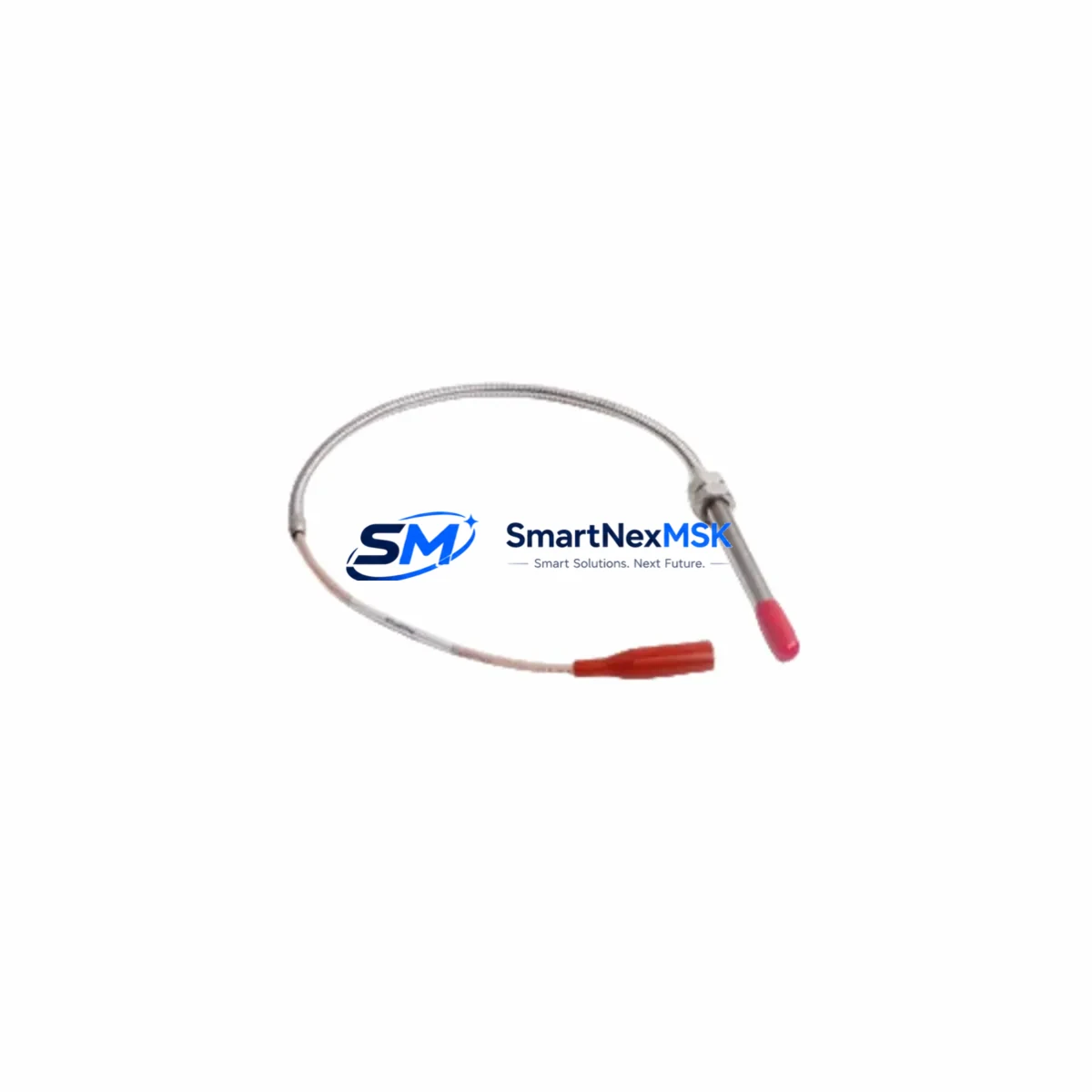
Begin with the PT2060/01 power supply module — verify output voltage stability under load, as a marginal power supply is a common root cause of intermittent monitor faults. Check the PT2060/02 backplane or rack chassis for connector pin corrosion, bent contacts, or mechanical damage that could cause poor module seating. Inspect the proximity probe and extension cable assembly (typically Bently Nevada 3300 XL or equivalent) for cable damage, connector oxidation, and correct gap voltage at the driver output.
Review the PT2060 relay output module associated with the replaced channel — relay contacts should be tested for continuity and correct trip logic before returning the system to service. If the PT2060 rack communicates with a DCS or safety system via a PT2060 communication module (Modbus RTU or similar), verify that the channel data is correctly mapped and that no communication timeout alarms are present after module reinsertion.
On the signal side, check any signal isolators or barriers installed between the PT2060 output and the DCS analog input card — these components age and can introduce offset errors that are mistakenly attributed to the monitor module itself. Inspect terminal blocks and field wiring in the control cabinet for loose terminations, particularly on the 4–20 mA loop and the relay wiring. Verify that fuse holders and circuit protection for the 24 VDC supply rail are intact and correctly rated.
For facilities running older PT2060 installations, this is also an appropriate time to assess the condition of the PT2060/10 or PT2060/20 I/O expansion modules if fitted, and to confirm that the HMI or operator panel displaying vibration trends is receiving valid data after the replacement. Proactive inspection of these surrounding components during a planned module swap significantly reduces the risk of a repeat fault and extends the effective service life of the entire protection system.
Site Replacement Workflow
Step 1 — Preparation: Confirm the PT2060/53 spare is the correct module variant for your rack slot by cross-referencing the existing module label and the system documentation. Verify that the replacement unit has passed pre-shipment testing (certificate included with shipment).
Step 2 — Safe Isolation: Follow your site LOTO (Lockout/Tagout) procedure. Inhibit the trip relay outputs at the DCS or safety system level to prevent spurious trips during module removal. Do not de-energize the entire rack if other channels must remain in service — the PT2060 supports hot-swap of individual modules in most configurations.
Step 3 — Module Removal: Release the module locking lever, extract the PT2060/53 from the rack slot, and inspect the backplane connector for damage before inserting the replacement.
Step 4 — Insertion and Verification: Seat the new PT2060/53 firmly until the locking lever engages. Power-up the channel and verify that the gap voltage reading on the front panel display is within the normal operating range (typically –10 VDC ±1 V for a correctly installed proximity probe). Confirm that alert and danger setpoints are correctly loaded — in most PT2060 configurations, setpoints are stored in the module and will need to be re-entered or downloaded from the configuration tool.
Step 5 — Functional Test and Return to Service: Simulate a vibration signal or use the module’s built-in test function to verify alert and danger relay operation. Confirm 4–20 mA output is correctly received at the DCS. Remove trip inhibits and return the channel to normal monitoring service. Document the replacement in the maintenance management system.
This workflow minimises downtime, ensures system compatibility, and provides a clear audit trail for compliance and reliability reporting.
Spare Parts Support FAQ
Q1: Is the PT2060/53 an original ProvibTech component or a third-party replacement?
The PT2060/53 supplied by SMARTNEXMSK is an original ProvibTech factory component, not a third-party copy or remanufactured unit. Each module undergoes pre-shipment functional testing and is supplied with a 12-month warranty covering manufacturing defects.
Q2: How do I verify compatibility with my existing PT2060 rack before ordering?
Compatibility is confirmed by the rack model number and slot designation shown on your system documentation or the existing module label. If you are unsure, provide us with your rack model, slot number, and the label details of the installed module — our technical team will confirm compatibility before shipment. We also recommend cross-referencing the PT2060 system manual for slot-specific module assignments.
Q3: What is the recommended spare parts holding strategy for a PT2060 installation?
For critical rotating machinery applications, we recommend holding a minimum of one PT2060/53 per installed rack as a hot spare, plus one PT2060/01 power supply module per site. For facilities with multiple PT2060 racks, a consolidated spare parts kit covering the most frequently replaced modules — including vibration monitor modules, relay output modules, and the power supply — provides the best balance of inventory cost and downtime risk reduction.
Q4: What does the 12-month warranty cover, and what is the returns process?
The 12-month warranty covers manufacturing defects and functional failures under normal operating conditions. It does not cover damage caused by incorrect installation, overvoltage, or physical mishandling. If a warranty claim is required, contact sales@smartnexmsk.com with the order reference and a description of the fault. We will arrange return shipping and either repair or replace the module at no additional cost.
© 2026 SMARTNEXMSK. All rights reserved.
Original Source: https://smartnexmsk.com
Contact: sales@smartnexmsk.com | +86 18259474341