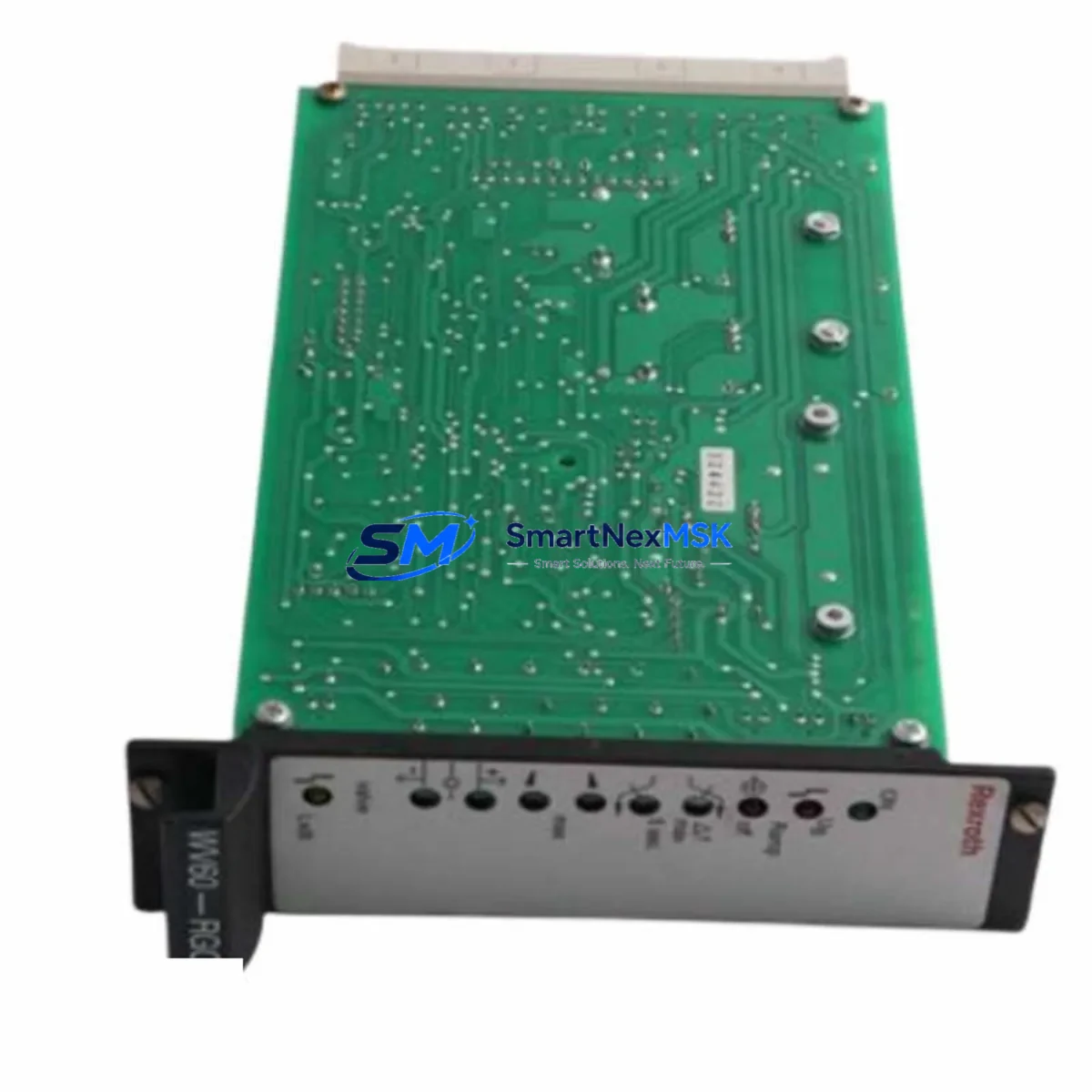
Rexroth SMP16-CPU086 Maintenance-Ready Spare for SMP16 Automation: Proportional Valve Control & Downtime Recovery
The Rexroth SMP16-CPU086 (A5E00344652) is an original proportional valve control board from Bosch Rexroth’s SMP16 series, engineered for precision closed-loop control of proportional hydraulic valves in demanding industrial automation environments. This CPU board serves as the core signal processing and command output unit within the SMP16 amplifier card system, translating PLC or DCS setpoint signals into accurate valve positioning commands. In hydraulic press lines, injection molding machines, steel mill roll gap control systems, and heavy industrial test rigs, the SMP16-CPU086 is a critical component whose failure results in immediate loss of proportional control — halting production and triggering unplanned downtime that can cost thousands per hour.
For maintenance engineers and spare parts procurement teams responsible for Rexroth hydraulic control systems, maintaining a verified, pre-tested SMP16-CPU086 spare is a non-negotiable element of any serious maintenance strategy. The SMP16 series has been deployed globally across long-lifecycle industrial installations, and original replacement boards are increasingly difficult to source through standard distribution channels. Securing a tested spare from a reliable supplier ensures that when a board failure occurs — whether from component aging, power surge, or environmental stress — restoration is measured in hours, not weeks.
Spare Maintenance Table
| Parameter | Specification |
|---|---|
| Part Number / SKU | SMP16-CPU086 / A5E00344652 |
| Brand | Bosch Rexroth |
| Series | SMP16 Proportional Valve Amplifier |
| Module Type | CPU / Signal Processing Control Board |
| Compatible Systems | SMP16 amplifier card rack; Rexroth proportional valve systems (4/2, 4/3 proportional directional valves) |
| Input Signal | ±10 V analog command (PLC/DCS analog output); enable/disable digital input |
| Output | Proportional solenoid driver signal; position feedback interface (LVDT/transducer) |
| Supply Voltage | 24 VDC (via SMP16 backplane power rail) |
| Operating Temperature | 0 °C to +55 °C (standard control cabinet environment) |
| Country of Origin | Germany |
| Weight | Approx. 1,250 g (packaged) |
| Condition | Original; new or refurbished-to-spec; functionally tested before shipment |
| Warranty | 12 Months — covers manufacturing defects and functional failure under normal operating conditions |
| Shipping | Global express shipping; ESD-safe anti-static packaging; traceable logistics |
| Application Environment | Hydraulic press control, injection molding, steel rolling mills, industrial test rigs, heavy machinery |
| Maintenance Recommendation | Inspect edge connector and card slot annually; verify analog calibration (zero/gain trim) after replacement; confirm enable signal logic before power-up |
Maintenance Planning for Continuous Operation
When an SMP16-CPU086 board is replaced during a planned or emergency maintenance window, experienced maintenance engineers treat the event as an opportunity for a broader SMP16 rack and hydraulic control cabinet audit. A single board failure is often a symptom of wider system stress, and inspecting adjacent components during the same downtime window maximizes the value of each maintenance intervention.
The SMP16 power supply card within the same amplifier rack should be the first component verified. An under-voltage or ripple condition on the 24 VDC backplane rail is a leading cause of CPU board logic errors and premature failure. Use a calibrated multimeter or oscilloscope to confirm the rail is within ±5% tolerance under load. Alongside this, the SMP16 interface card (the analog I/O front-end board in the same rack) should be inspected for connector oxidation and signal integrity — a degraded interface card can cause the replacement CPU086 to exhibit the same fault symptoms as the failed unit, leading to misdiagnosis.
The 24 VDC DIN-rail power supply feeding the SMP16 rack — commonly a Phoenix Contact QUINT or Siemens SITOP unit — should be load-tested to confirm output stability. Voltage sag under peak solenoid switching loads is a known stress factor for proportional amplifier electronics. In the same cabinet inspection, the analog signal wiring from the PLC analog output module to the SMP16 command input should be checked for shield continuity and grounding — a broken shield on the ±10 V reference cable introduces noise that manifests as valve hunting or instability, which is frequently misattributed to a faulty CPU board.
For systems using LVDT position transducers for closed-loop valve position feedback, the transducer cable and connector at the valve body should be inspected for mechanical damage, moisture ingress, and connector pin integrity. A drifting LVDT signal will cause the SMP16-CPU086 to command continuous correction, accelerating board wear. The proportional solenoid coil resistance on the valve itself should also be measured (typically 20–40 Ω depending on valve model) — a shorted or open coil will damage the solenoid driver stage of a new CPU board if not identified before power-up.
Where the SMP16 system interfaces with a Siemens S7-300/400 PLC or a Beckhoff CX series controller via analog output modules, the PLC analog output channel should be verified with a reference meter before reconnecting to the SMP16 input — a faulty PLC output card can inject out-of-range signals that immediately stress the replacement board. Terminal block connections (Phoenix Contact or Weidmüller DIN-rail terminals) on the signal and power wiring should be torque-checked and inspected for discoloration indicating thermal stress. Finally, any signal isolators on the analog command path — used in high-EMI environments near large VFDs or welding equipment — should be verified for correct gain and offset calibration, as these are often overlooked during board replacement and can cause persistent control errors post-commissioning.
Site Replacement Workflow
Step 1 — Pre-replacement documentation: Record all potentiometer settings on the existing SMP16-CPU086 board (zero trim, gain trim, ramp time, dither frequency and amplitude if applicable). Photograph the board face and note the position of all adjustment trimmers. These settings are not stored digitally and must be manually replicated on the replacement board. Also record any active fault codes from the PLC or HMI operator panel before de-energizing.
Step 2 — Safe isolation: Follow your site LOTO (Lockout/Tagout) procedure. De-energize the SMP16 rack power supply and the hydraulic power unit (HPU) before removing the board. Confirm zero pressure in the hydraulic circuit at the manifold gauge before working near valve wiring. The SMP16-CPU086 is not hot-swap capable — power must be removed before extraction.
Step 3 — Board extraction and inspection: Release the card ejector levers and extract the CPU086 board from the rack slot. Inspect the gold-plated edge connector for contamination or bent contacts. Inspect the rack slot connector for the same. Clean with IPA 99% if required. Note the board revision marking for compatibility confirmation with the replacement unit.
Step 4 — Replacement installation and calibration: Insert the new SMP16-CPU086 A5E00344652 firmly until the ejector levers lock. Reconnect all front-panel wiring. Before power-up, set the zero and gain trimmers to the documented positions from Step 1. Apply power to the rack only (HPU isolated) and verify the enable LED and status indicators show normal startup. Use a calibrated signal source to inject a known command signal and verify the solenoid driver output responds correctly before reconnecting the valve.
Step 5 — Commissioning and return to service: Re-enable the HPU and perform a slow ramp test of the proportional valve through its full stroke range. Verify position feedback (LVDT signal) tracks the command signal within specification. Confirm no fault codes are active on the PLC or HMI. Document the replacement in the maintenance log with the new board serial number and calibration settings. This workflow supports legacy system life extension — many SMP16-based hydraulic control systems from the 1990s and 2000s remain in productive service, and sourcing original CPU boards is the most cost-effective alternative to a full system retrofit.
Spare Parts Support FAQ
Q1: Is the SMP16-CPU086 A5E00344652 compatible with all SMP16 rack configurations?
The A5E00344652 is the standard CPU board for the SMP16 proportional valve amplifier series. Compatibility depends on the specific SMP16 rack variant and the interface card installed in the adjacent slot. We recommend confirming the rack model number and existing board revision before ordering. Our technical team can assist with compatibility verification based on your system nameplate and existing board markings.
Q2: What functional testing is performed before shipment?
Every SMP16-CPU086 unit undergoes power-on self-test verification, analog input/output signal path testing, and visual PCB inspection before dispatch. Units are shipped in ESD-safe anti-static packaging with individual test documentation where applicable. The 12-month warranty covers functional failure under normal operating conditions from the date of receipt.
Q3: How should I manage SMP16-CPU086 spare stock for a multi-press or multi-axis installation?
For facilities operating 4 or more SMP16-controlled axes, maintaining a minimum of one CPU086 spare per 4 axes is a widely adopted strategy in the hydraulic press and injection molding maintenance community. Given that the SMP16 series is in the legacy phase of its product lifecycle, proactive sourcing is strongly advisable — original board availability from standard distribution is declining. We offer long-term supply agreements and reserved stock programs for high-volume buyers.
Q4: Can I replace the SMP16-CPU086 without recalibrating the entire proportional valve system?
In most cases, yes — provided the trimmer settings from the original board are accurately documented and replicated on the replacement unit (see Step 1 of the Site Replacement Workflow above). The SMP16 system stores calibration in hardware (potentiometers), not in non-volatile digital memory, so physical documentation of trim positions before removal is essential. A brief functional test with a signal source before reconnecting the hydraulic load is always recommended to confirm calibration before returning the system to production.
© 2026 SMARTNEXMSK. All rights reserved.
Original Source: https://smartnexmsk.com
Contact: sales@smartnexmsk.com | +86 18259474341