ROFIN RCULX500 101110998 Maintenance-Ready Spare for RCU-LX Laser Automation
When a laser marking or cutting line goes down, every minute of unplanned downtime translates directly into lost production and delayed delivery schedules. The ROFIN RCULX500 (Part Number 101110998), also referenced as the RCU-LX-500 Perform SP02, is the original remote control unit designed for ROFIN’s RCU-LX series laser systems. Keeping a verified spare of this unit on the shelf is one of the most cost-effective decisions a maintenance engineer can make for any facility running ROFIN laser equipment.
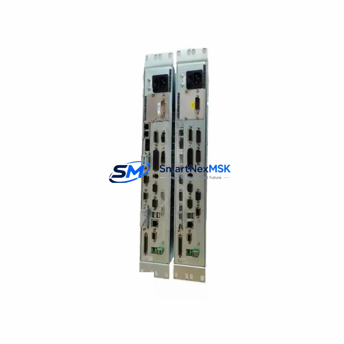
This unit serves as the primary operator interface and remote control hub for ROFIN Perform SP02 laser sources and compatible RCU-LX platform configurations. It manages laser parameter input, status feedback, interlock signaling, and communication with the host PLC or CNC controller. When the RCULX500 fails — whether due to display degradation, keypad wear, internal communication faults, or power surge damage — the laser source itself becomes inoperable, halting the entire production cell.
Spare Maintenance Table
| Parameter | Specification / Detail |
|---|---|
| Part Number | RCULX500 / 101110998 |
| Series | RCU-LX-500 / Perform SP02 |
| Brand | ROFIN |
| Product Type | Laser Remote Control Unit |
| Origin | Germany |
| Weight | 2,300 g (approx.) |
| Interface Compatibility | RCU-LX series laser sources, Perform SP02 platform |
| Communication | RS-232 / proprietary ROFIN serial link |
| Installation | Panel-mount or control cabinet integration |
| Power Input | 24 VDC (via control cabinet supply) |
| Replacement Scope | Direct drop-in for failed or degraded RCULX500 units |
| Maintenance Recommendation | Inspect annually; replace on display or keypad fault |
| Warranty | 12-Month Warranty — tested before shipment |
Maintenance Planning for Continuous Operation
Effective maintenance planning for a ROFIN laser system goes well beyond replacing the RCULX500 in isolation. Maintenance engineers should treat this replacement as an opportunity to inspect the entire laser control cabinet and associated electrical infrastructure. The 24 VDC control power supply feeding the RCU-LX-500 should be load-tested; a marginal power supply is a common root cause of intermittent remote control faults and should be replaced proactively alongside the RCULX500.
The RS-232 or proprietary serial communication cable connecting the RCULX500 to the laser source controller is another frequent failure point. These cables are subject to repeated flexing, connector wear, and EMI-induced signal degradation in industrial environments. Inspecting and replacing the communication cable during the same maintenance window eliminates a common callback fault. Similarly, the terminal blocks and wiring harness inside the control cabinet — particularly the interlock loop wiring and E-stop relay connections — should be checked for loose terminations and insulation wear.
If the facility uses a PLC to coordinate the laser cell, the I/O module handling the laser ready signal, fault output, and trigger inputs should be verified for correct signal levels after the RCULX500 is replaced. In many installations, a Siemens S7-300 or S7-1200 series digital I/O module, or an equivalent Allen-Bradley 1756 ControlLogix I/O card, interfaces directly with the laser interlock and trigger circuit. Confirming that these I/O channels are reading correctly after replacement prevents nuisance faults during restart.
For facilities running ROFIN laser sources integrated with a CNC controller or motion platform, the fiber optic link or EtherCAT communication module between the laser controller and the motion system should also be inspected. A degraded fiber connector or a faulty EtherCAT node can cause the laser to appear unresponsive even after a successful RCULX500 replacement. Checking the signal integrity of these links during the maintenance window saves significant diagnostic time.
The HMI panel — whether a ROFIN-supplied operator terminal or a third-party touchscreen running the laser cell SCADA — should be verified for correct communication with the new RCULX500. Screen calibration, parameter display accuracy, and alarm acknowledgment functions should all be confirmed before returning the system to production. Facilities using a Weintek or Siemens TP series HMI for laser cell visualization should update the device driver or communication settings if the replacement unit has a different firmware revision.
Finally, the fuse and circuit protection components in the laser control cabinet — including the 24 VDC branch fuse, the interlock relay, and any signal isolation modules in the I/O circuit — should be inspected and replaced if they show signs of thermal stress or aging. A Phoenix Contact or Weidmüller signal isolator in the laser trigger circuit, for example, can degrade silently and cause erratic laser firing behavior that is easily misdiagnosed as a remote control unit fault.
Site Replacement Workflow
Replacing the ROFIN RCULX500 on-site is a straightforward procedure when the correct spare is available and the replacement is planned in advance. Begin by documenting the current laser parameter settings displayed on the existing RCULX500 — output power, pulse frequency, pulse width, and any application-specific presets — since these will need to be re-entered after the replacement unit is installed.
Power down the laser system following the manufacturer’s lockout/tagout procedure. Disconnect the communication cable and the 24 VDC power connector from the existing RCULX500. Remove the unit from its panel mount or cabinet bracket, noting the orientation and cable routing for reference. Install the replacement RCULX500, reconnect the power and communication cables, and restore power to the control cabinet.
On first power-up, verify that the replacement unit displays the correct firmware version and that the laser source responds to remote control commands. Re-enter the documented laser parameters and run a test firing sequence at reduced power to confirm that the laser output, interlock, and trigger functions are all operating correctly. Log the replacement in the facility’s maintenance management system, noting the part number, serial number of the replacement unit, and the date of installation.
This structured replacement workflow minimizes the risk of overlooked wiring errors, parameter mismatches, or communication faults that can extend downtime beyond the actual replacement time. With a pre-tested RCULX500 spare on hand and a documented procedure in place, most facilities can complete the replacement and return the laser cell to production within two to four hours of fault identification.
Spare Parts Support FAQ
Q: Is the RCULX500 (P/N 101110998) compatible with all RCU-LX-500 Perform SP02 laser systems?
A: Yes. The RCULX500 with part number 101110998 is the standard remote control unit for the RCU-LX-500 Perform SP02 platform. It is a direct replacement for the original unit. If your system uses a different RCU-LX variant, please confirm the part number with our technical team before ordering.
Q: How is the unit tested before shipment?
A: Every RCULX500 unit is powered on and functionally tested prior to shipment. Communication interface, display, keypad, and power input are all verified. A test report is available upon request. Units are shipped in protective packaging to prevent transit damage.
Q: What does the 12-month warranty cover?
A: The 12-month warranty covers manufacturing defects and functional failures under normal operating conditions. It does not cover damage caused by incorrect installation, overvoltage, or physical impact. Warranty claims are processed promptly with replacement or repair at no additional cost.
Q: Can you supply the RCULX500 for long-term maintenance contracts or blanket orders?
A: Yes. We maintain stock of the RCULX500 and can support scheduled delivery programs, blanket purchase orders, and consignment arrangements for facilities with ongoing maintenance requirements. Contact our sales team to discuss volume pricing and delivery scheduling.
© 2026 SMARTNEXMSK. All rights reserved.
Original Source: https://smartnexmsk.com
Contact: sales@smartnexmsk.com | +86 18259474341