Rorze RD-023MS Retrofit-Ready Stepper Drive for RD Series Control Systems
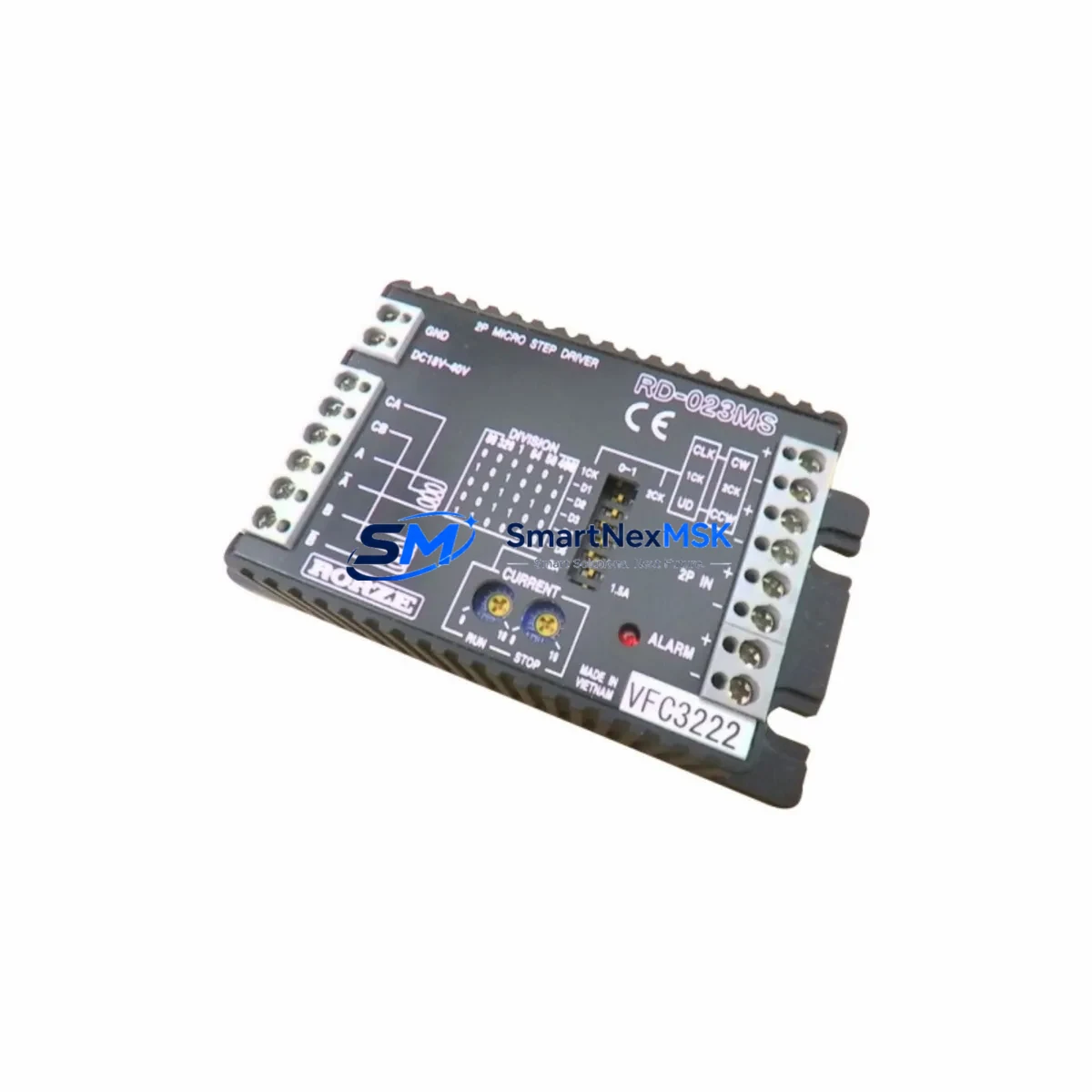
The Rorze RD-023MS is a compact, high-performance microstepping motor drive engineered for seamless integration into existing RD Series automation platforms. Whether you are replacing an end-of-life unit on a legacy semiconductor handling system, upgrading a wafer transfer robot controller, or restoring motion control continuity after an unexpected drive failure, the RD-023MS delivers the electrical compatibility, signal fidelity, and mechanical form factor required for a low-risk, minimum-downtime retrofit.
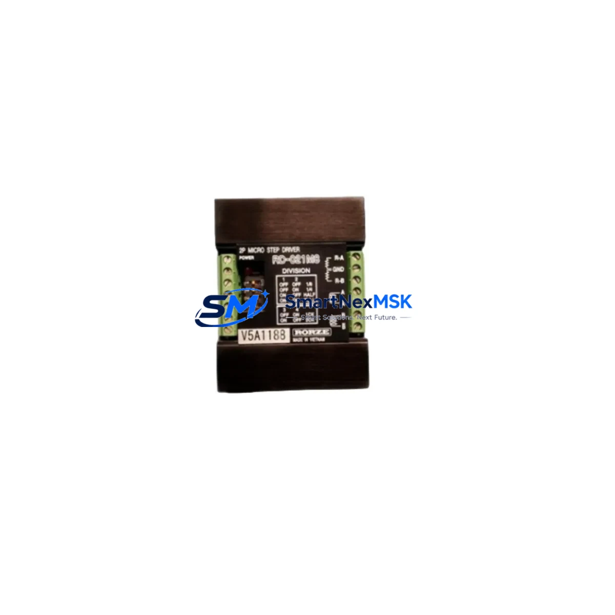
Rorze automation systems are widely deployed across semiconductor fabs, flat panel display lines, and precision assembly environments. As original RD Series drives age beyond their rated service life, sourcing verified replacement units becomes critical to maintaining production uptime. The RD-023MS addresses this need directly — it accepts standard Pulse/Direction command signals, supports selectable microstep resolutions, and interfaces with the same 2-phase bipolar stepper motors used throughout the RD Series platform, including motors paired with Rorze RC-417 and RC-420 robot controllers.
Upgrade Compatibility Table
| Parameter | RD-023MS Specification | Retrofit Notes |
|---|---|---|
| Drive Type | Microstepping, 2-phase bipolar | Direct replacement for legacy RD Series stepper drives |
| Command Interface | Pulse/Direction (P/D) | Compatible with existing Rorze RC-series controller signal outputs |
| Supply Voltage | DC 24V / 48V (model-dependent) | Verify cabinet PSU capacity before installation; check Rorze PS-series power supply ratings |
| Motor Connector | 4-wire bipolar terminal block | Confirm terminal pitch matches existing motor cable harness |
| Microstep Resolution | Selectable via DIP switch | Match original resolution setting to preserve program pulse counts |
| Mounting | DIN rail / panel mount | Same footprint as predecessor RD Series drives; no bracket modification required |
| Communication | Standalone (no fieldbus) | For RS-232/RS-485 networked axes, pair with Rorze RC-series motion controller |
| Alarm Output | Open-collector fault signal | Wire to existing PLC input (e.g., Mitsubishi FX3U or Omron CP1H) for fault monitoring |
| Warranty | 12 Months | Covered from date of shipment; includes functional verification before dispatch |
Retrofit Planning for Existing Automation Systems
A successful RD-023MS retrofit begins well before the drive arrives on-site. Engineers should pull the original electrical drawings and confirm the control cabinet’s DC bus voltage — typically supplied by a Rorze PS-series or equivalent 24V/48V DIN-rail power supply — can sustain the RD-023MS peak current demand without tripping overcurrent protection. If the cabinet houses multiple axes, calculate the aggregate load across all installed drives, including any Rorze RD-028MS or RD-035MS units on adjacent axes, to ensure the power supply headroom is adequate.
Next, inspect the motor cable harness. The RD-023MS uses a standard 4-wire bipolar terminal block, and the winding phase assignment (A+, A−, B+, B−) must match the original drive’s pinout. Swapping a phase pair will reverse motor direction and can corrupt position references stored in the Rorze RC-series controller. Label each wire before disconnecting the old drive.
On the signal side, verify that the Pulse/Direction output from the motion controller — whether a Rorze RC-417, RC-420, or a third-party controller such as a Mitsubishi MR-J4 servo amplifier used on adjacent axes — meets the RD-023MS input voltage and frequency specifications. Pulse trains exceeding the drive’s maximum input frequency will cause missed steps and position error alarms. If the system uses an Omron NJ/NX series machine controller for coordinated multi-axis motion, confirm the axis object pulse output settings match the new drive’s step resolution.
For systems that include a Rorze HMI panel or a third-party GOT2000 touch panel for operator interaction, review all axis jog speed, home offset, and soft-limit parameters stored in the HMI recipe data. These values are typically expressed in pulse counts and must be recalculated if the microstep resolution DIP switch setting on the RD-023MS differs from the original drive. Updating the HMI screen data before commissioning prevents nuisance limit alarms during the first powered test.
Where the control network includes RS-485 multi-drop communication to peripheral devices — such as Rorze RR-series RFID readers or barcode scanners on a wafer cassette station — confirm that the drive replacement does not disturb the network termination resistor or node addressing. The RD-023MS itself does not participate in the RS-485 network, but physical cable routing through the same conduit can introduce noise if shielding is disturbed during installation.
Finally, if the system includes a Rorze RI-series I/O expansion module for additional digital inputs and outputs, verify that the drive fault relay wiring to the I/O module is restored correctly after the swap. A missed fault wire is one of the most common causes of post-retrofit alarm suppression, where a real drive fault goes undetected by the supervisory PLC.
Downtime Control During System Migration
Minimizing production downtime during an RD-023MS swap requires a structured hot-swap protocol. Before powering down the axis, use the Rorze RC-series controller’s position read command to record the current absolute position of the affected axis. Save this value alongside the current program step number and any active recipe parameters. If the system runs a SEMI-standard wafer handling sequence, note the cassette slot index and robot arm extension state so the sequence can be resumed from a known safe position after the drive is replaced.
Power down only the affected axis drive — not the entire controller — where the cabinet design permits individual axis isolation. This preserves the live program state in the RC-series controller’s volatile memory and avoids a full system reboot, which on some older Rorze platforms can take several minutes and requires re-homing all axes. If individual axis power isolation is not possible, perform a controlled program halt, save all axis positions to non-volatile memory, and document the halt point in the maintenance log.
After installing the RD-023MS, perform a low-speed jog test before enabling full-speed automatic operation. Confirm motor direction, check for abnormal vibration or heat, and verify that the drive’s alarm output is correctly read by the supervisory PLC. Run a complete home cycle and compare the homed position against the pre-swap reference. If the delta exceeds the system’s position tolerance — typically ±0.1 mm on precision wafer handling stages — investigate the microstep resolution setting and motor phase wiring before resuming production.
Every RD-023MS unit shipped by SMARTNEXMSK undergoes functional verification testing prior to dispatch, reducing the risk of receiving a non-operational unit and extending unplanned downtime. The included 12-month warranty covers both component failure and workmanship defects, providing a documented quality assurance baseline for your maintenance records.
Retrofit Support FAQ
Q1: Is the RD-023MS a direct drop-in replacement for my existing RD Series stepper drive?
In most RD Series applications, yes. The RD-023MS shares the same Pulse/Direction command interface, bipolar motor terminal layout, and DIN rail mounting footprint as the drives it replaces. You should verify the supply voltage rating and confirm the microstep resolution DIP switch matches your original configuration before powering up.
Q2: How do I confirm wiring compatibility before installation?
Compare the terminal block pinout in the RD-023MS datasheet against your existing cabinet wiring diagram. Pay particular attention to the motor phase assignment (A+, A−, B+, B−) and the Pulse/Direction signal voltage level. If your original wiring documentation is unavailable, contact our technical team with the cabinet model number and we will assist with pinout cross-referencing.
Q3: Will I need to modify my PLC program or HMI screens after the replacement?
If the microstep resolution setting on the RD-023MS matches the original drive, no program changes are required. If the resolution differs, pulse count parameters in the motion controller and any HMI recipe data referencing axis travel distances must be recalculated. We recommend performing a dry-run simulation in the controller’s offline programming environment before live commissioning.
Q4: What does the 12-month warranty cover, and how is it claimed?
The 12-month warranty covers functional failure under normal operating conditions, including drive output stage faults, control logic failures, and workmanship defects. It does not cover damage caused by incorrect wiring, overvoltage, or physical impact. To initiate a warranty claim, contact sales@smartnexmsk.com with your order number, a description of the fault symptom, and any alarm codes displayed by the drive or supervisory controller.
© 2026 SMARTNEXMSK. All rights reserved.
Original Source: https://smartnexmsk.com
Contact: sales@smartnexmsk.com | +86 18259474341