SANMEI RT-001AXE Retrofit-Ready AC Servo Driver: Seamless Compatibility for RT Series Control System Upgrades
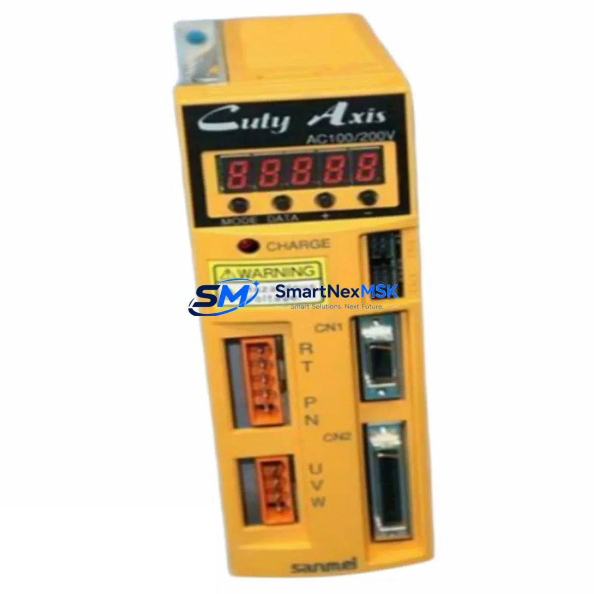
The SANMEI RT-001AXE is a high-performance AC servo driver engineered for direct retrofit integration into existing RT Series automation platforms. Whether you are replacing an end-of-life servo drive, modernizing a legacy control cabinet, or recovering a production line from an unplanned failure, the RT-001AXE delivers verified electrical compatibility, matched terminal pinout, and full protocol continuity — minimizing engineering risk and reducing unplanned downtime to the absolute minimum.
Industrial facilities running RT Series servo systems frequently encounter the challenge of sourcing discontinued components. The RT-001AXE is stocked specifically to address this gap. It is a direct functional replacement for legacy RT Series servo drives that have reached end-of-life or are no longer available through standard distribution channels. Before installation, engineers should confirm the input power specification (single-phase or three-phase, 200V or 400V class), rated output current, encoder interface type (incremental or absolute), and the communication protocol in use — whether that is RS-485 Modbus, CANopen, or a proprietary RT Series fieldbus variant.
Terminal wiring compatibility is a critical verification step during any servo drive retrofit. The RT-001AXE maintains the standard RT Series terminal layout for main power (R/S/T), motor output (U/V/W), brake resistor (P/D), and control signal terminals (SIG, COM, ALM, RDY). Engineers replacing an older RT Series unit should map the existing wiring harness against the RT-001AXE terminal diagram before energizing the system. In most cases, the existing motor cable, encoder cable, and I/O wiring can be reused without modification, which significantly reduces retrofit labor time.
Upgrade Compatibility Table
| Parameter | Legacy RT Series Drive | SANMEI RT-001AXE | Retrofit Note |
|---|---|---|---|
| Power Input | 200V / 400V Class | 200V / 400V Class | Verify supply voltage before installation |
| Encoder Interface | Incremental / Absolute | Incremental / Absolute | Confirm encoder type and cable pinout |
| Communication Protocol | RS-485 / CANopen / Proprietary | RS-485 / CANopen Compatible | Verify baud rate and node address settings |
| Terminal Layout | Standard RT Series | Matched RT Series Layout | Existing wiring harness typically reusable |
| Mounting Format | DIN Rail / Panel Mount | DIN Rail / Panel Mount | Check cabinet depth clearance |
| Control Mode | Position / Speed / Torque | Position / Speed / Torque | Re-verify gain parameters after swap |
| Regenerative Braking | Internal / External Resistor | Internal / External Resistor | Reuse existing brake resistor if rated correctly |
| Warranty | — | 12 Months | Covered from date of shipment |
Retrofit Planning for Existing Automation Systems
A successful RT-001AXE retrofit requires a structured pre-installation review of the surrounding control architecture. In a typical RT Series control cabinet, the servo driver operates alongside a programmable logic controller — commonly an RT Series PLC or a compatible third-party controller — connected via a backplane bus or discrete I/O wiring. Before removing the failed drive, document the existing parameter settings using the drive’s front panel keypad or the RT Series servo configuration software. Key parameters include position loop gain, speed loop gain, acceleration/deceleration ramp times, electronic gear ratio, and fault output logic.
The control cabinet typically also houses an RT Series power supply module providing 24VDC logic power to the drive’s control circuit, separate from the main AC power input. Verify that the 24VDC supply capacity is sufficient for the RT-001AXE’s control circuit draw. In multi-axis systems, the shared DC bus or common power supply module must be assessed for total load capacity after the replacement unit is installed.
For systems using an RT Series HMI panel, the servo status screens, alarm displays, and jog control pages are typically linked to PLC data registers that mirror drive status words. After replacing the drive, verify that the PLC program’s axis control function blocks and motion instructions are compatible with the RT-001AXE’s command interface. In most RT Series architectures, the servo drive receives position commands via pulse-and-direction signals or via a fieldbus motion profile — both of which the RT-001AXE supports natively.
I/O expansion modules connected to the same control rack — such as RT Series digital input modules, analog output modules, or high-speed counter modules — are unaffected by the servo drive replacement and do not require reconfiguration. However, if the system uses a communication module for PROFIBUS, EtherNet/IP, or CC-Link connectivity, confirm that the network topology and node addressing remain intact after the drive swap. Programming cables used for drive parameter backup and restore should be verified for compatibility with the RT-001AXE’s USB or RS-232 configuration port before the maintenance window begins.
Downtime Control During System Migration
Minimizing production downtime during a servo drive replacement requires preparation before the maintenance window opens. Begin by backing up the existing drive parameters to a laptop or USB memory device using the RT Series configuration utility. If the original drive is non-functional and parameter backup is not possible, reconstruct the parameter set from the machine’s electrical drawings, commissioning records, or the OEM’s default parameter table for the specific motor and load combination.
During the physical swap, label all wiring connections before disconnection. Photograph the terminal block layout and encoder connector orientation. Install the RT-001AXE into the cabinet, reconnect all wiring in sequence — control power first, then encoder, then I/O signals, and finally main AC power — and restore the parameter set before energizing the motor circuit. Perform a no-load jog test at low speed to verify encoder feedback direction and drive response before returning the axis to automatic control under the PLC program. This structured commissioning sequence typically allows a trained technician to complete a single-axis RT Series servo drive replacement within two to four hours, keeping the production line impact to a single shift.
All RT-001AXE units are pre-tested under load conditions prior to shipment and include a factory test report. Each unit is covered by a 12-month warranty from the date of shipment, covering manufacturing defects and functional failures under normal operating conditions.
Retrofit Support FAQ
Q: Is the RT-001AXE a direct drop-in replacement for all RT Series servo drives?
A: The RT-001AXE is compatible with the majority of RT Series servo drive applications. Confirm the power class (200V or 400V), rated current, and encoder interface type match your existing motor and system specifications before ordering. Our technical team can assist with cross-reference verification.
Q: Can I reuse the existing motor cable and encoder cable from the original RT Series drive?
A: In most cases, yes. The RT-001AXE uses the standard RT Series terminal and connector layout. Verify the encoder cable pinout against the RT-001AXE wiring diagram, particularly for absolute encoder battery backup connections if applicable.
Q: What commissioning steps are required after installing the RT-001AXE?
A: Restore the backed-up parameter set, verify encoder feedback polarity with a low-speed jog test, confirm I/O signal logic levels, and check communication link status if the drive is connected to a fieldbus network. Re-run the auto-tuning routine if load conditions have changed since the original commissioning.
Q: What does the 12-month warranty cover?
A: The warranty covers manufacturing defects and functional failures under normal operating conditions for 12 months from the date of shipment. Units that have been physically damaged, modified, or operated outside their rated specifications are not covered. Warranty claims are processed with a replacement unit dispatched upon fault confirmation.
© 2026 SMARTNEXMSK. All rights reserved.
Original Source: https://smartnexmsk.com
Contact: sales@smartnexmsk.com | +86 18259474341