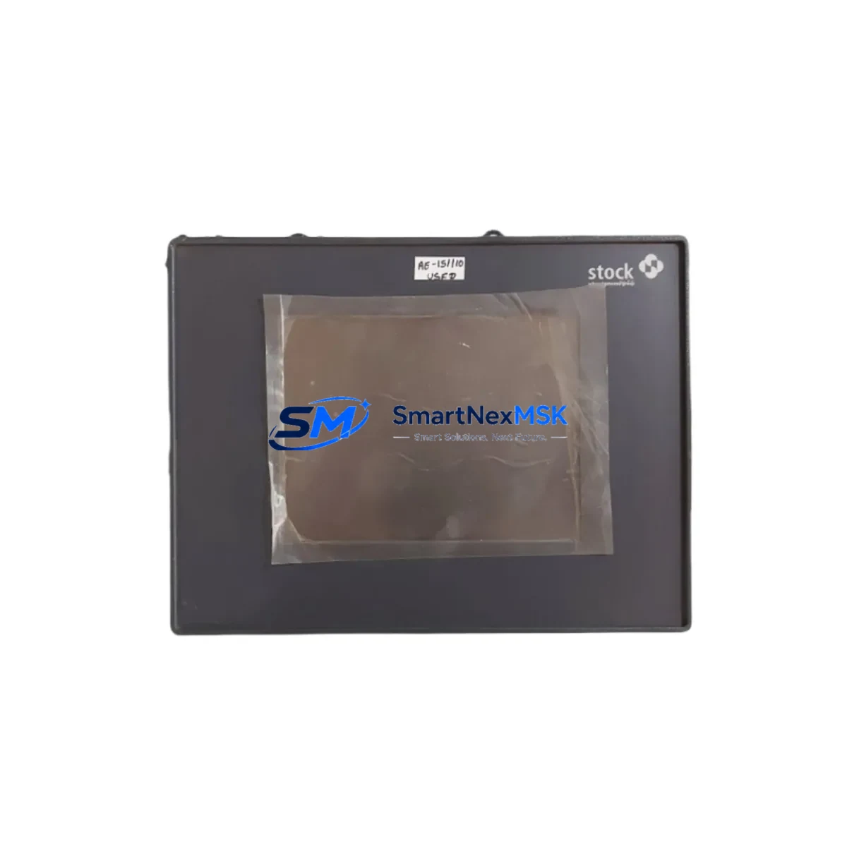
Schenck VLB20105 V003048.B02 Retrofit-Ready Vibration Balancing Module for VLB Series Control Systems
The Schenck VLB20105 V003048.B02 is a retrofit-ready vibration balancing control module engineered for seamless integration into existing Schenck VLB Series automation and balancing machine control systems. As original Schenck VLB-series hardware reaches end-of-life and spare parts become increasingly scarce, this module provides a verified drop-in replacement path that preserves your existing wiring harness, terminal block layout, and backplane interface — minimizing engineering rework and unplanned downtime during system migration.
Designed for industrial environments where continuous operation is critical, the VLB20105 V003048.B02 supports direct substitution in control cabinets previously housing legacy Schenck balancing controllers. Engineers undertaking a retrofit project must verify power supply capacity (typically 24 VDC rail), confirm terminal wiring compatibility against the original I/O assignment sheet, and validate backplane slot addressing before powering the replacement module. The module’s communication interface is compatible with standard Schenck measurement and evaluation electronics, ensuring that existing HMI screens and operator panels do not require reprogramming in most retrofit scenarios.
When planning a system upgrade, it is essential to document the original program logic stored in the balancing controller before removal. If the existing system uses a Schenck CAB 920 or CAB 930 evaluation unit, the VLB20105 V003048.B02 integrates within the same rack architecture, reducing the need for additional backplane adapters or communication bridge modules. For installations that include a Schenck BN 3000 or BN 4000 series balancing machine, this module maintains signal-level compatibility with the measurement chain, including proximity sensors, vibration transducers, and phase reference pickups already installed on the production line.
Upgrade Compatibility Table
| Parameter | Details |
|---|---|
| SKU / Part Number | VLB20105 V003048.B02 |
| Brand / Manufacturer | Schenck |
| Compatible Series | Schenck VLB Series Balancing Control Systems |
| Module Function | Vibration Balancing Control Module |
| Installation Type | Backplane / Rack-mount (VLB Series chassis) |
| Power Supply Requirement | 24 VDC (verify rail capacity before installation) |
| Terminal Wiring | Compatible with original VLB Series terminal block layout |
| Communication Interface | Schenck proprietary measurement bus (VLB Series) |
| HMI / Operator Panel | Compatible — no HMI screen reprogramming required in standard retrofit |
| Replaces / Supersedes | Legacy Schenck VLB Series vibration balancing modules (EOL) |
| Commissioning Requirement | Module address verification, I/O mapping check, signal calibration |
| Origin | Germany |
| Warranty | 12 Months |
| Shipping | Fast global shipping, export-compliant packaging |
Retrofit Planning for Existing Automation Systems
A successful retrofit of the Schenck VLB20105 V003048.B02 begins with a thorough audit of the existing control cabinet. Before removing the legacy module, engineers should photograph all terminal connections and record the current module address settings on the backplane. In systems where the VLB controller communicates with a Schenck CAB 920 evaluation unit, the communication link parameters — including baud rate and node address — must be noted and replicated on the replacement module during commissioning.
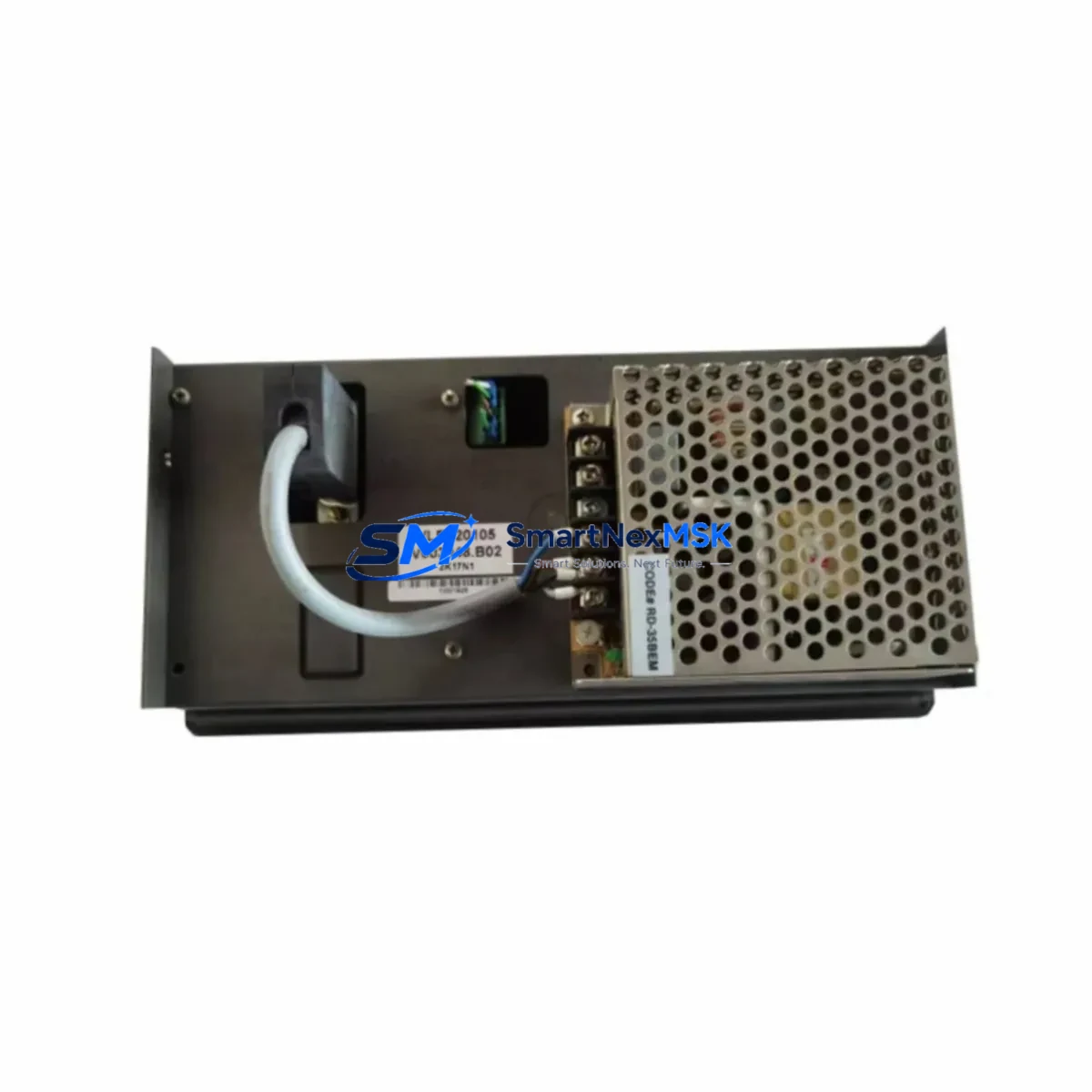
For production lines that integrate a Schenck BN 3000 balancing machine or BN 4000 series, the vibration measurement chain typically includes piezoelectric vibration sensors, a phase reference sensor (optical or magnetic), and a signal conditioning unit. These field devices remain unchanged during a VLB module swap, provided the replacement module’s input impedance and signal range specifications are matched. If the control cabinet also houses a Schenck power supply module (such as a 24 VDC DIN-rail PSU), verify that the available current capacity accommodates the VLB20105 V003048.B02’s inrush and steady-state current draw before energizing the system.
In multi-axis balancing systems or production lines with expanded I/O requirements, the retrofit may also involve reviewing the Schenck I/O expansion module configuration to ensure that digital output assignments for unbalance correction triggers and measurement-complete signals remain correctly mapped. If the existing system uses a Schenck operator terminal or a third-party HMI panel connected via serial or Ethernet, confirm that the communication protocol (typically RS-232, RS-485, or Profibus DP) is supported by the replacement module’s firmware version.
Where the original system included a Schenck programming cable or USB-to-serial adapter for parameter configuration, the same interface is typically used to upload calibration data and measurement parameters to the VLB20105 V003048.B02. Retain all original parameter files and calibration records, as these will be required during the post-installation functional test. For systems that previously relied on a Schenck CAB 930 controller in a supervisory role, verify that the higher-level control logic and interlock sequences remain intact after the module replacement.
Downtime Control During System Migration
Minimizing production downtime during a VLB module replacement requires careful pre-staging and a structured commissioning sequence. Before the scheduled maintenance window, prepare the Schenck VLB20105 V003048.B02 by verifying its firmware version, performing a bench-level power-on test, and confirming that all factory calibration data is intact. Having the replacement module pre-configured with the correct node address and communication parameters reduces on-site installation time significantly.
During the changeover, follow a structured sequence: isolate the control cabinet from the main power supply, discharge any residual voltage on the backplane, remove the legacy module, install the VLB20105 V003048.B02 into the same rack slot, and reconnect all terminal wiring according to the documented wiring diagram. After power restoration, perform a step-by-step I/O verification — confirm that all digital inputs (start, stop, reset, measurement trigger) and digital outputs (unbalance OK, fault relay, correction complete) respond correctly before resuming automatic balancing cycles.
To protect the original program logic and measurement parameters, always back up the existing controller configuration to a laptop or USB drive using the Schenck programming software before beginning the physical swap. This backup serves as the recovery baseline if the commissioning process encounters unexpected compatibility issues. In most standard VLB Series retrofit scenarios, the total planned downtime — from cabinet isolation to first successful balancing cycle — can be contained within a single maintenance shift when the replacement module is pre-staged and the engineering team is familiar with the system architecture.
Retrofit Support FAQ
Q1: Is the Schenck VLB20105 V003048.B02 a direct drop-in replacement for the original VLB Series module?
A: In the majority of VLB Series installations, the VLB20105 V003048.B02 is a direct replacement with no mechanical or wiring modifications required. Engineers should verify the backplane slot type, terminal block pinout, and module address settings against the original system documentation before installation to confirm full compatibility.
Q2: What commissioning steps are required after installing the replacement module?
A: After physical installation, the commissioning sequence includes: verifying the module address on the backplane, uploading the saved calibration and parameter file via the Schenck programming cable, performing an I/O functional test (all digital inputs and outputs), running a no-load measurement cycle to confirm signal integrity, and completing a loaded balancing test with a known reference rotor before returning the machine to production.
Q3: Will the existing HMI screens and operator panel displays need to be updated?
A: In standard retrofit scenarios where the VLB20105 V003048.B02 replaces a same-generation VLB Series module, HMI screens and operator panel graphics typically do not require modification. If the system is being upgraded from an older VLB generation with a different communication protocol version, a minor HMI parameter update may be required — consult the system’s original HMI configuration file for reference.
Q4: What warranty and post-shipment support is provided?
A: Every Schenck VLB20105 V003048.B02 unit supplied by SMARTNEXMSK is covered by a 12-month warranty against manufacturing defects and functional failures under normal operating conditions. Each unit undergoes pre-shipment functional testing before dispatch. Our technical team is available to support wiring verification, commissioning guidance, and compatibility questions throughout the warranty period.
© 2026 SMARTNEXMSK. All rights reserved.
Original Source: https://smartnexmsk.com
Contact: sales@smartnexmsk.com | +86 18259474341