SHARP JW-213S Retrofit-Ready AC Output Module for JW Series Control Systems
When aging production lines depend on legacy SHARP JW Series programmable logic controllers, sourcing a reliable, drop-in replacement for the JW-213S AC output module becomes a critical priority. Whether you are managing a planned control cabinet upgrade or responding to an unexpected module failure, the JW-213S delivers the wiring compatibility, output performance, and installation simplicity that retrofit engineers demand. At SMARTNEXMSK, we maintain verified stock of the JW-213S with full pre-shipment functional testing and a 12-month warranty, ensuring your migration project stays on schedule and within budget.
Upgrade Compatibility Table
| Parameter | Specification / Notes |
|---|---|
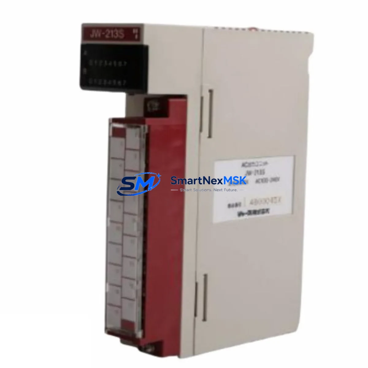
| SKU / Model | JW-213S |
| Brand / Series | SHARP / JW Series PLC |
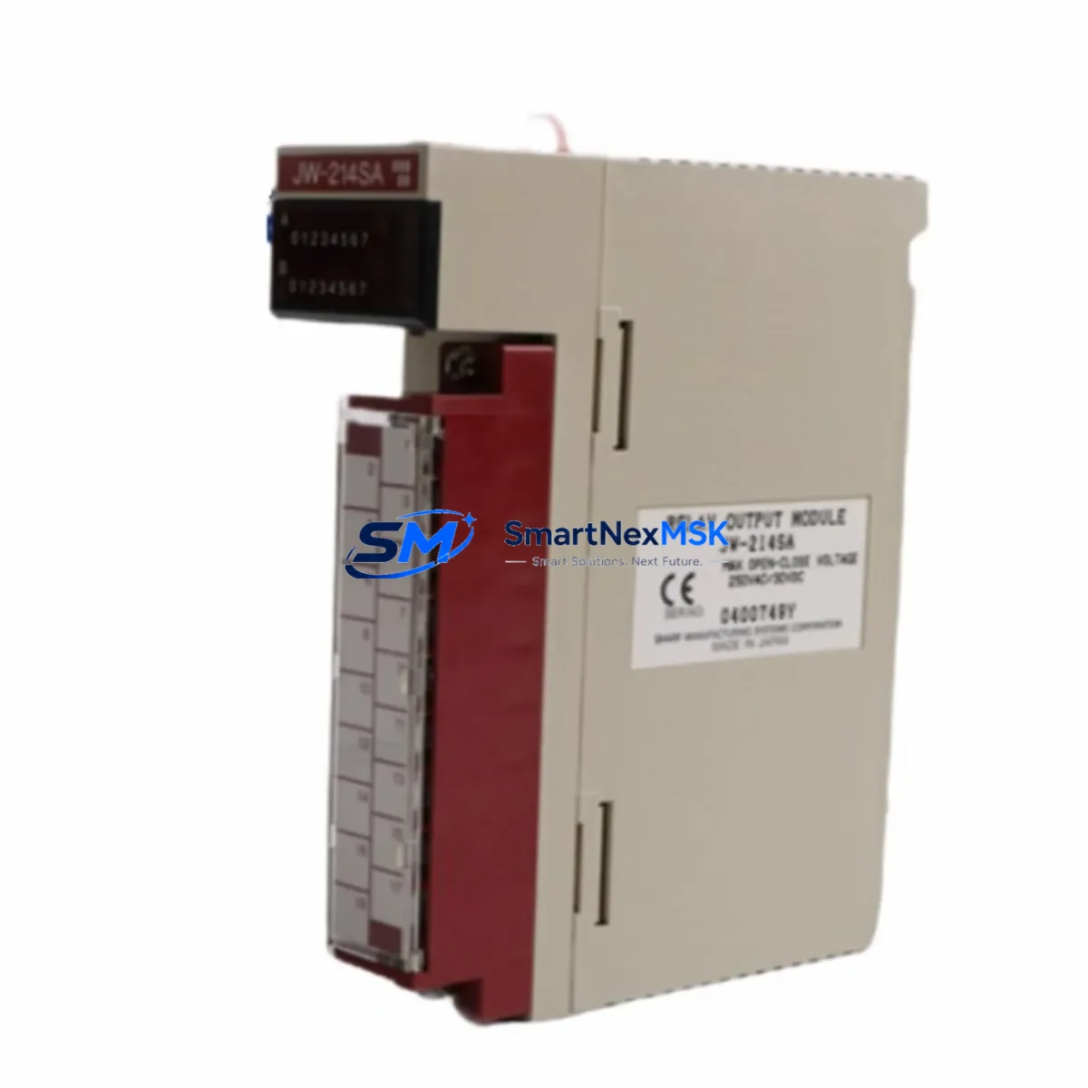
| Module Type | AC Output Module |
| Output Points | 16 points (AC load switching) |
| Rated Output Voltage | 85–264V AC |
| Output Current per Point | 0.5A (typical); consult original JW Series manual for derating |
| Backplane Interface | JW Series standard bus connector — direct slot replacement |
| Terminal Wiring | Screw-terminal block; pin-compatible with JW-21 and JW-32 racks |
| Communication Compatibility | Transparent to JW Series CPU scan cycle; no protocol change required |
| Replacement Recommendation | Direct drop-in for JW-213S; verify rack slot address before power-up |
| Commissioning Focus | Confirm module address DIP switches match original configuration |
| Origin | Japan |
| Weight | 220 g |
| Warranty | 12-Month Warranty — covered from date of shipment |
Retrofit Planning for Existing Automation Systems
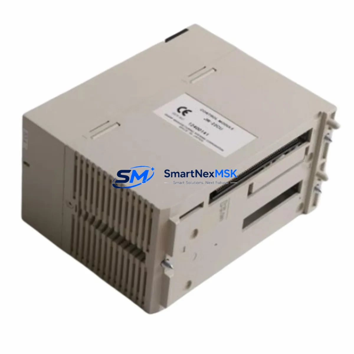
A successful JW-213S retrofit begins well before the module arrives on site. Engineers working with SHARP JW Series control cabinets should first document the existing rack layout, noting which slots are occupied by the JW-22PU power supply module, the JW-32CUH CPU unit, and any installed JW-214T DC input modules or JW-215T DC output modules. Understanding the full I/O map prevents address conflicts when the replacement JW-213S is seated into the backplane.
Before removing the failed module, capture the current DIP switch settings on the original JW-213S. These switches define the module’s slot address within the JW Series rack and must be replicated exactly on the replacement unit. If the original module is completely non-functional, cross-reference the address against the PLC program comments or the JW Series hardware configuration manual. Mismatched addresses will cause the JW-32CUH CPU to flag an I/O configuration error at startup, preventing normal scan execution.
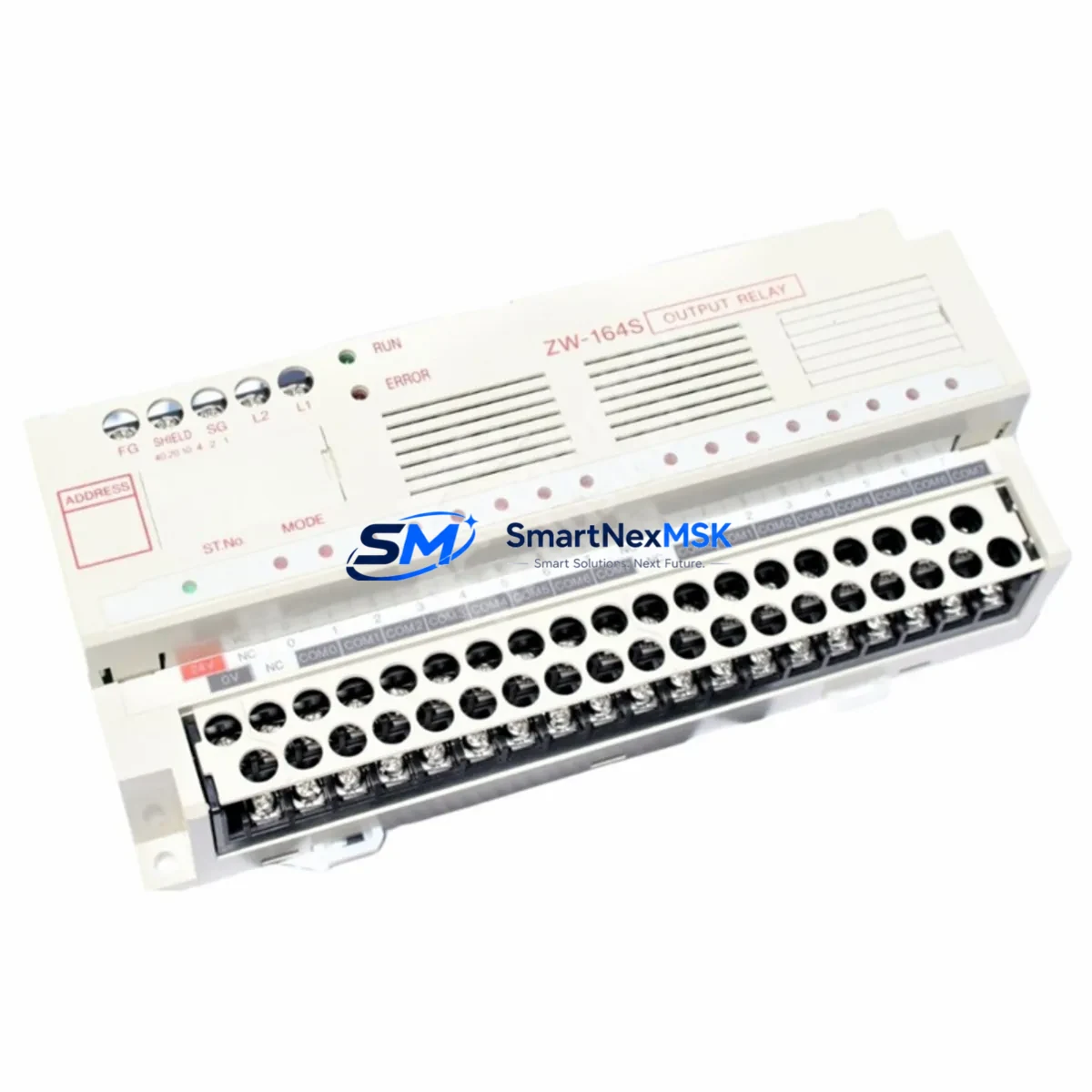
Wiring adaptation is straightforward because the JW-213S uses a standard screw-terminal block that is physically and electrically compatible with the JW-21 and JW-32 rack families. Technicians should label each AC load wire before disconnection and verify insulation integrity with a megohmmeter before reconnecting to the new module. For cabinets that also house a JW-13PG programming console or a connected JW-50H handheld programmer, ensure the CPU is placed in STOP mode and program memory is backed up to a JW-SP memory cassette before any hardware change.
Communication links running over the SHARP JW-10CM serial communication module or a connected RS-232C programming cable do not require reconfiguration after an output module swap, as the JW-213S is transparent to the CPU’s communication scan. However, if the cabinet integrates a third-party HMI via a JW-21CM link module, confirm that the HMI tag addresses referencing the output coils remain valid after the module replacement. A brief online monitoring session using the JW Series ladder programming software will confirm that all output coil states are correctly reflected before returning the system to AUTO mode.
Downtime Control During System Migration
Minimizing unplanned downtime during a JW-213S replacement requires a structured hot-swap protocol. Begin by scheduling the swap during a planned maintenance window and pre-staging the replacement module with DIP switches pre-configured to match the original. Keep the JW-22PU power supply energized but place the CPU in STOP mode to freeze output states and prevent unintended actuator movement during the physical swap.
Once the new JW-213S is seated and the terminal block is reconnected, perform a visual inspection of all AC load wiring before restoring power. Power up the rack and observe the module’s LED status indicators — a steady RUN LED with no ERR indication confirms successful initialization. Transition the CPU from STOP to RUN mode and monitor the first 10–15 scan cycles using online ladder monitoring to verify that all 16 output points respond correctly to their associated coil instructions. Document the swap in the cabinet maintenance log, including the module serial number, date, and technician name, to support future warranty claims and audit requirements.
For sites where continuous production makes even a brief STOP mode unacceptable, SMARTNEXMSK can advise on partial-rack redundancy strategies using dual JW Series racks with cross-connected I/O, allowing one rack to remain in RUN while the other undergoes maintenance. Contact our technical team for site-specific retrofit planning support.
Retrofit Support FAQ
Q1: Is the JW-213S a direct drop-in replacement for the original SHARP JW-213S module?
Yes. The JW-213S supplied by SMARTNEXMSK is an original SHARP component with identical form factor, backplane connector, terminal block layout, and DIP switch configuration. No mechanical modification or wiring adaptation is required for standard JW-21 and JW-32 rack installations.
Q2: What pre-shipment testing is performed on each JW-213S unit?
Every JW-213S undergoes functional output switching tests across all 16 points, insulation resistance verification, and visual inspection for connector integrity before shipment. A test report is available on request. Units that do not pass all test criteria are quarantined and not shipped.
Q3: How do I confirm wiring and address compatibility before installation?
Record the DIP switch positions on the original module and replicate them on the replacement. Verify terminal block wiring against the original cabinet drawing. If drawings are unavailable, use the JW Series hardware manual to decode the address from the switch pattern. SMARTNEXMSK technical support can assist with address decoding if needed.
Q4: What does the 12-month warranty cover, and how is a claim processed?
The 12-month warranty covers manufacturing defects and functional failures under normal operating conditions from the date of shipment. To initiate a claim, contact sales@smartnexmsk.com with the order number, module serial number, and a description of the failure. SMARTNEXMSK will arrange return shipping and provide a replacement or refund within the warranty period.
© 2026 SMARTNEXMSK. All rights reserved.
Original Source: https://smartnexmsk.com
Contact: sales@smartnexmsk.com | +86 18259474341