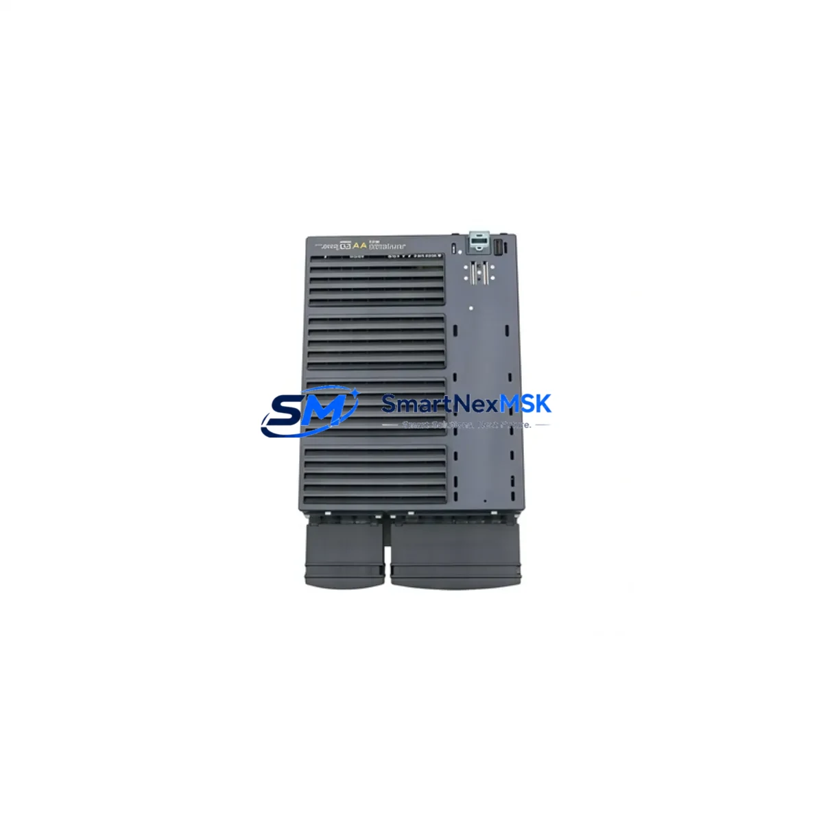
Siemens 6DS1222-8BA Retrofit-Ready Interface for TELEPERM M Control Systems
The Siemens 6DS1222-8BA is a proven N-AT Interface Module engineered for the TELEPERM M Distributed Control System (DCS) platform. As legacy TELEPERM M installations approach end-of-support milestones, the 6DS1222-8BA remains one of the most sought-after retrofit components for engineers tasked with sustaining, upgrading, or partially migrating aging process control infrastructure. SMARTNEXMSK maintains verified stock of this module, fully tested and backed by a 12-month warranty, to support planned and emergency retrofit projects across chemical, petrochemical, power generation, and heavy industrial facilities.
Whether you are replacing a failed unit on a live production line, building a spare-parts buffer ahead of a scheduled turnaround, or executing a phased migration from TELEPERM M toward a modern DCS or hybrid control architecture, the 6DS1222-8BA provides the interface continuity your system requires. Each unit shipped by SMARTNEXMSK undergoes pre-shipment functional verification to confirm backplane communication integrity, terminal block condition, and module addressing compatibility before dispatch.
Upgrade Compatibility Table
| Parameter | Details |
|---|---|
| SKU / Part Number | 6DS1222-8BA |
| Brand / Manufacturer | Siemens |
| Compatible Platform | TELEPERM M DCS (AS 220, AS 230, AS 235) |
| Module Function | N-AT Interface — analog/digital signal conditioning and backplane communication |
| Backplane Interface | TELEPERM M standard rack bus; compatible with 6DS1 series rack assemblies |
| Installation Requirement | Direct slot insertion into TELEPERM M subrack; no hardware modification required for like-for-like replacement |
| Communication Compatibility | SINEC H1 / Industrial Ethernet gateway-compatible via CS 275 or CS 275B communication processor |
| Replacement Recommendation | Direct drop-in replacement for failed or end-of-life 6DS1222-8BA units; verify module address assignment before insertion |
| Commissioning Notes | Confirm DIP switch / jumper address settings match original module; re-download function block assignments from ES 100 or PG engineering station if required |
| Warranty | 12 months from shipment date — covers manufacturing defects and functional failure under normal operating conditions |
Retrofit Planning for Existing Automation Systems
A successful 6DS1222-8BA retrofit begins well before the module arrives on site. Engineers should audit the existing TELEPERM M subrack configuration, documenting the slot position, module address, and wiring terminations of the unit being replaced. The terminal block wiring — typically 40-pin or 64-pin depending on the subrack generation — must be photographed and mapped before removal to ensure accurate reconnection. Power supply capacity within the control cabinet should be verified: the TELEPERM M power supply modules (such as the 6DS1600 series PSU) must provide sufficient 24 VDC rail current to support the reinstated interface module without marginal loading.
In systems where the 6DS1222-8BA interfaces with analog I/O marshalling, engineers should cross-reference the connected 6DS1300 series analog input/output modules to confirm signal range compatibility (4–20 mA, 0–10 V, thermocouple, or RTD) has not drifted due to aging field wiring. Where the TELEPERM M communicates upstream to a supervisory SCADA or DCS historian via a CS 275B communication processor, the communication link should be tested in loopback before the new module is inserted to isolate any pre-existing network faults from the retrofit activity itself.
For sites executing a phased migration toward Siemens SIMATIC PCS 7 or a third-party DCS, the 6DS1222-8BA can serve as a bridge component, maintaining TELEPERM M I/O integrity while migration engineering proceeds on parallel racks. In this scenario, the 6DS1700 series digital I/O modules and any installed 6DS1400 series function modules should be inventoried simultaneously, as they are frequently replaced in the same project scope. HMI screens built on SIMATIC WinCC or legacy OS 525 operator stations may require tag remapping if module addresses are reassigned during the retrofit — this step is often overlooked and is a common source of post-commissioning alarms.
Where the control system includes a 6DS1800 series communication module for PROFIBUS DP or SINEC L2 integration, verify that the new 6DS1222-8BA does not conflict with existing bus segment addressing. Programming cables and engineering software (ES 100 or STEP 5 for hybrid SIMATIC S5 co-installations) should be on hand during commissioning to allow rapid function block re-download if the module’s internal configuration is not retained from the original unit. Rack assemblies from the 6DS1100 subrack family should also be inspected for backplane connector wear, as degraded connectors are a frequent root cause of intermittent faults that are misdiagnosed as module failure.
Downtime Control During System Migration
Minimizing unplanned downtime during a 6DS1222-8BA replacement requires a structured hot-swap or cold-swap protocol depending on the process criticality. For non-critical loops, a cold-swap during a scheduled maintenance window is preferred: isolate the affected I/O channels at the marshalling cabinet, remove the failed module, insert the replacement, restore wiring, and perform a channel-by-channel functional test before returning the loop to automatic control. For critical process loops — such as those governing reactor temperature, pressure safety, or turbine speed — a parallel bypass strategy should be implemented: route the affected signals through a temporary SIMATIC S7-300 or portable data acquisition unit to maintain monitoring continuity while the TELEPERM M slot is serviced.
Original program logic stored in the TELEPERM M AS 220 or AS 235 automation station is retained in battery-backed RAM and is not affected by module hot-removal in most configurations; however, engineers should confirm battery backup status on the automation station before proceeding. After module insertion, allow a full initialization cycle (typically 30–90 seconds) before forcing outputs or acknowledging alarms. Document the as-found and as-left module address settings, terminal wiring, and any deviation from the original configuration in the plant maintenance management system to support future audits and spare-parts planning.
Retrofit Support FAQ
Q1: Is the 6DS1222-8BA a direct drop-in replacement for all TELEPERM M subrack configurations?
In the majority of TELEPERM M installations using AS 220, AS 230, or AS 235 automation stations, the 6DS1222-8BA is a direct slot-compatible replacement. Engineers should verify the module address (set via DIP switches or jumpers on the module face) matches the original unit’s address assignment before powering up. No firmware flashing is required for like-for-like replacement.
Q2: What commissioning steps are required after installing a replacement 6DS1222-8BA?
After physical installation and wiring reconnection, perform a channel-by-channel I/O verification from the engineering station (ES 100 or equivalent). Confirm that all function block assignments are correctly loaded and that the module appears on the TELEPERM M system bus without fault indication. Test communication continuity to any upstream CS 275B or SINEC H1 gateway before returning the system to automatic operation.
Q3: Can the 6DS1222-8BA be used in a hybrid system alongside SIMATIC S5 or PCS 7 components?
Yes, in phased migration projects the 6DS1222-8BA can coexist with SIMATIC S5 CPUs and PCS 7 OS servers within the same control cabinet, provided bus segment addressing is managed carefully. Signal handoff between TELEPERM M and SIMATIC platforms is typically handled via hardwired I/O cross-connections or a dedicated gateway module rather than direct backplane integration.
Q4: What does the 12-month warranty cover, and how is it claimed?
The 12-month warranty covers manufacturing defects and functional failure under normal industrial operating conditions from the date of shipment. It does not cover damage resulting from incorrect installation, overvoltage, or physical impact. To initiate a warranty claim, contact SMARTNEXMSK at sales@smartnexmsk.com with the order reference, a description of the fault, and photographic evidence of the installation. Replacement or repair will be arranged within 5 business days of claim confirmation.
© 2026 SMARTNEXMSK. All rights reserved.
Original Source: https://smartnexmsk.com
Contact: sales@smartnexmsk.com | +86 18259474341