Siemens 6SL3224-0BE31-5UA0: Retrofit-Ready Single Motor Module for SINAMICS S120 Control Systems
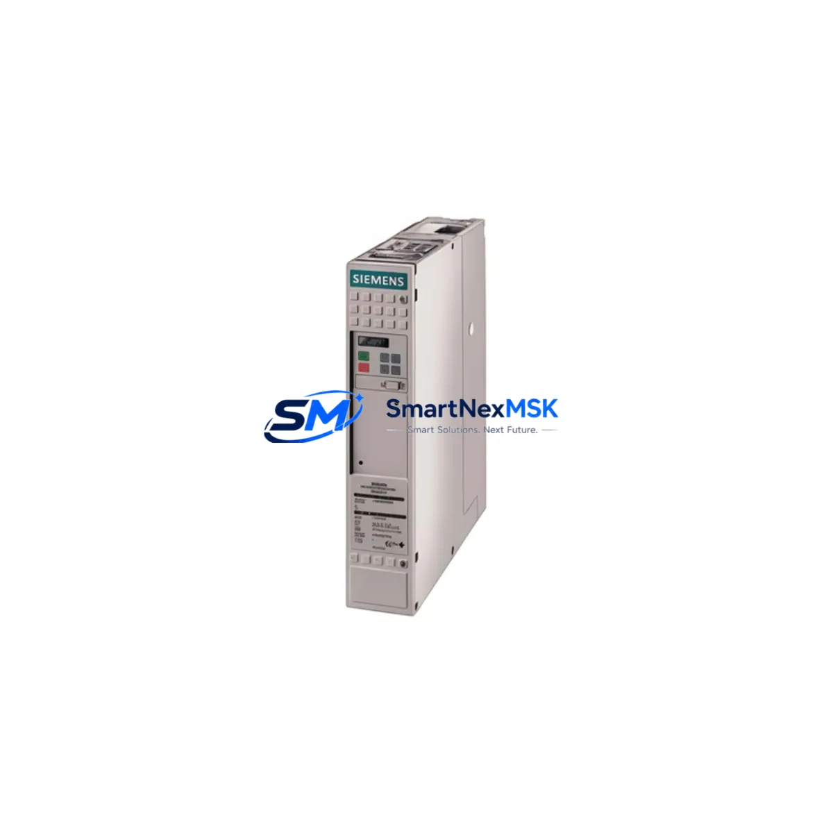
The Siemens 6SL3224-0BE31-5UA0 is a 15 kW Single Motor Module designed for the SINAMICS S120 booksize drive platform. As legacy S120 installations age and OEM support windows narrow, this module has become one of the most sought-after retrofit and replacement components in industrial automation. Whether you are upgrading a discontinued axis drive, recovering from an unplanned failure, or modernizing a multi-axis CNC or servo control cabinet, the 6SL3224-0BE31-5UA0 delivers a verified drop-in upgrade path with minimal re-engineering.
SMARTNEXMSK maintains ready stock of the 6SL3224-0BE31-5UA0, sourced from authorized channels and subject to full pre-shipment functional testing. Each unit ships with a 12-month warranty covering manufacturing defects and operational failures under normal industrial use conditions.
Upgrade Compatibility Table
| Parameter | 6SL3224-0BE31-5UA0 Specification | Retrofit Notes |
|---|---|---|
| Rated Output Power | 15 kW | Verify motor nameplate; de-rate if ambient >40 °C |
| DC Link Voltage | 600 V DC (nominal) | Must match existing Active Line Module or Smart Line Module output |
| Drive Format | Booksize | Compatible with standard S120 booksize chassis and power bus |
| Drive-CLiQ Interface | 2 × Drive-CLiQ ports | Topology must be re-mapped in STARTER or TIA Portal after swap |
| Installation | DIN rail / panel mount, booksize | Existing mounting holes and bus adapter compatible |
| Communication | Drive-CLiQ (PROFIBUS/PROFINET via CU320-2) | No protocol change required; CU320-2 DP or CU320-2 PN retains configuration |
| Replacement Candidates | 6SL3224-0BE31-1UA0, 6SL3224-0BE30-7UA0 | Confirm power rating and firmware version before substitution |
| Commissioning Tool | STARTER V5.x / TIA Portal V15+ | Upload existing project; re-run motor identification (MDS) |
| Warranty | 12 Months | Covers manufacturing defects; excludes physical damage |
Retrofit Planning for Existing Automation Systems
Replacing a motor module in a live S120 system requires careful pre-work to avoid extended downtime and protect existing program logic. Before removing the faulty 6SL3224-0BE31-5UA0 or its predecessor, engineers should back up the complete drive project from the CU320-2 Control Unit using STARTER or TIA Portal. The project file contains all axis parameters, speed setpoints, torque limits, and encoder configurations that would otherwise need to be re-entered manually.
On the power side, confirm that the upstream Active Line Module (such as a 6SL3130-series ALM) or Smart Line Module has sufficient DC link capacity to support the 15 kW module alongside other axes sharing the same booksize chassis. Check the total connected load against the line module’s rated output current. If the cabinet also houses a 6SL3040-series Control Supply Module, verify that its 24 V DC output can sustain the additional Drive-CLiQ node after the new module is inserted.
Terminal wiring on the motor side should be documented before disconnection. The U2, V2, W2 motor output terminals and the PE bonding point must be re-torqued to specification after installation. If the original installation used a 6SL3060-series DRIVE-CLiQ Hub Module to fan out topology, the hub’s port assignment may shift when the new module is inserted, requiring a topology update in the commissioning tool.
For systems using SIMOTICS servo motors with integrated encoders (SMC20 or SMC30 Sensor Module Cabinet-Mounted), the encoder cable routing and SMC address assignment should be verified against the original axis map. In multi-axis gantry or coordinated motion applications, the axis number assigned to the 6SL3224-0BE31-5UA0 in the S7-300 or S7-1500 PLC program must remain consistent to avoid axis swap faults at startup.
If the retrofit involves migrating from an older MASTERDRIVES MC or early-generation S120 booksize to the current hardware revision, pay attention to firmware compatibility. The CU320-2 firmware version must support the hardware revision of the new motor module. Use the Siemens Compatibility Tool or consult the firmware release notes before flashing. In some cases, a 6SL3054-series CompactFlash card with updated firmware is required before the new module will be recognized on the Drive-CLiQ network.
Where the control cabinet also contains a SIMATIC HMI panel (such as a TP700 or KTP900 Basic), verify that any drive fault screens referencing the axis name or drive object number still map correctly after the module swap. HMI variable tables linked to drive parameters via PROFINET or PROFIBUS should be tested in simulation mode before returning the line to production.
Downtime Control During System Migration
Minimizing production interruption during a motor module replacement starts with preparation, not speed. Before the maintenance window opens, stage the replacement 6SL3224-0BE31-5UA0 on the bench and confirm it powers up correctly with a temporary 24 V DC supply to the electronics bus. This bench check, combined with the pre-shipment functional test performed by SMARTNEXMSK, eliminates the risk of installing a second faulty unit.
During the swap, keep the CU320-2 Control Unit powered if the cabinet design allows it. Many S120 booksize installations permit hot-swap of individual motor modules while the control unit remains live, provided the axis is safely disabled via the PLC and the DC link is discharged. Consult the S120 Hardware Installation Manual (Siemens document A5E03264351) for your specific chassis revision before attempting a live swap.
After physical installation, the commissioning sequence should follow a defined order: restore the drive project from backup, run the automatic topology detection in STARTER or TIA Portal, confirm the new module appears at the correct Drive-CLiQ address, and then execute a motor data identification run (stationary MDS) before enabling the axis under load. This sequence typically takes 30–60 minutes for a single axis and can be completed within a planned shift-change window, keeping unplanned downtime to a minimum.
For sites with strict change-management requirements, SMARTNEXMSK can provide a pre-configured module with customer-supplied parameter files loaded and verified before shipment, further reducing on-site commissioning time.
Retrofit Support FAQ
Q1: Is the 6SL3224-0BE31-5UA0 a direct replacement for the 6SL3224-0BE31-1UA0?
A: The two modules share the same booksize form factor and Drive-CLiQ interface, but differ in rated output power (15 kW vs. 11 kW). A direct substitution is possible only if the motor and application load are within the 15 kW module’s operating range. Always verify motor nameplate data and confirm the line module has sufficient headroom before substituting a higher-rated module.
Q2: What commissioning steps are required after installing the replacement module?
A: After physical installation, restore the drive project backup to the CU320-2, run automatic topology detection, confirm the module’s Drive-CLiQ address, and perform a stationary motor data identification (MDS). If the firmware version on the new module differs from the original, update via the CompactFlash card before running MDS. Full axis function should be validated under no-load conditions before returning to production.
Q3: How do I verify wiring compatibility before powering up?
A: Compare the terminal layout of the replacement module against the original wiring diagram. Confirm U2/V2/W2 motor output connections, PE bonding, and the 24 V DC electronics supply connector. Check that the DC link bus adapter is fully seated and that all Drive-CLiQ cables are secured. Use a multimeter to verify insulation resistance on the motor cable before energizing the DC link.
Q4: What does the 12-month warranty cover?
A: The warranty covers manufacturing defects and operational failures under normal industrial use conditions for 12 months from the date of shipment. It does not cover damage resulting from incorrect installation, overvoltage events, environmental contamination, or unauthorized modification. SMARTNEXMSK provides a pre-shipment functional test report with each unit; retain this document as part of your warranty claim record.
© 2026 SMARTNEXMSK. All rights reserved.
Original Source: https://smartnexmsk.com
Contact: sales@smartnexmsk.com | +86 18259474341