Siemens 6ES7307-1BA00-0AA0 Maintenance-Ready Spare for PS307 Automation
The Siemens 6ES7307-1BA00-0AA0 is an original PS307 series power supply module engineered for the SIMATIC S7-300 programmable logic controller platform. In industrial maintenance environments, unplanned downtime caused by a failed power supply module can cascade across an entire control cabinet — halting production lines, triggering safety shutdowns, and generating costly recovery cycles. Stocking a verified replacement unit of the 6ES7307-1BA00-0AA0 is a foundational element of any responsible spare parts strategy for facilities running S7-300-based automation systems.
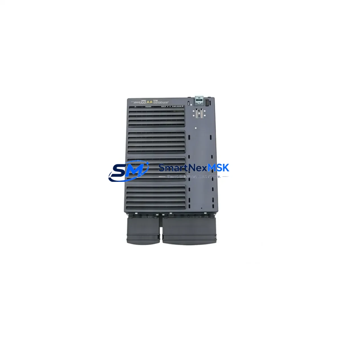
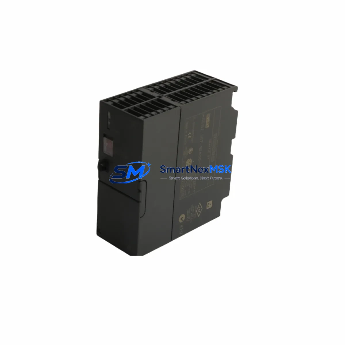
This module delivers a regulated 24 VDC output at 2 A, accepting a wide-range AC input (120/230 VAC, 50/60 Hz), making it compatible with global power infrastructure without hardware modification. Its compact rail-mount form factor integrates directly into standard S7-300 control cabinets, and the module’s diagnostic LED indicators allow maintenance engineers to confirm operational status at a glance during routine cabinet inspections.
For maintenance and procurement engineers managing aging S7-300 installations, the 6ES7307-1BA00-0AA0 represents a critical line item. As Siemens has transitioned newer platforms toward the S7-1500 series, original PS307 modules are increasingly sourced through specialist industrial spare parts channels. Each unit supplied by SMARTNEXMSK is tested prior to shipment, ships with a 12-month warranty, and is traceable to verified supply chains — ensuring you receive a genuine, functional component rather than a counterfeit or refurbished substitute.
Spare Maintenance Table
| Parameter | Specification |
|---|---|
| SKU / Part Number | 6ES7307-1BA00-0AA0 |
| Brand | Siemens |
| Series | PS307 (SIMATIC S7-300) |
| Product Type | PLC Power Supply Module |
| Input Voltage | 120 / 230 VAC, 50/60 Hz (wide-range) |
| Output Voltage | 24 VDC |
| Output Current | 2 A |
| Output Power | 48 W |
| Mounting | DIN Rail (S7-300 standard profile rail) |
| Dimensions (W×H×D) | 50 × 125 × 120 mm (approx.) |
| Weight | 260 g |
| Country of Origin | Germany |
| Compatibility | SIMATIC S7-300 CPU modules, SM signal modules, CP communication processors |
| Operating Temperature | 0 °C to +60 °C |
| Protection Class | IP20 |
| Certifications | CE, UL (per Siemens product documentation) |
| Diagnostic Indicators | 24 VDC OK LED, overload/short-circuit protection LED |
| Warranty | 12 Months (SMARTNEXMSK) |
| Pre-shipment Testing | Yes — functional output voltage and load test performed |
| Condition | Original / New |
Maintenance Planning for Continuous Operation
When a PS307 power supply module fails or shows signs of degradation — output voltage drift, intermittent shutdowns, or overload trips — the replacement workflow should extend beyond simply swapping the 6ES7307-1BA00-0AA0. A thorough maintenance engineer will use the event as an opportunity to audit the entire power distribution chain within the S7-300 control cabinet.
Begin by inspecting the 24 VDC bus wiring and terminal blocks (such as Weidmüller or Phoenix Contact DIN rail terminals) for signs of oxidation, loose crimps, or thermal discoloration — these are common root causes of premature power supply stress. Next, verify the condition of the S7-300 CPU module (e.g., CPU 314 or CPU 315-2 DP) and confirm that its backplane connector is seated correctly, as a damaged backplane can cause abnormal current draw that shortens power supply life.
Check all installed SM321/SM322 digital I/O modules and SM331/SM334 analog I/O modules for field wiring short circuits — a shorted field device can repeatedly trip the PS307’s overload protection. If the cabinet includes CP343-1 or CP343-1 Advanced Ethernet communication processors, confirm their power draw is within the PS307’s 2 A budget, particularly in multi-rack configurations where a IM360/IM361 interface module pair is used to extend the rack.
For cabinets with relay output modules or external relay banks (e.g., Siemens 3RT or 3RH contactor series), inspect coil suppression circuits and verify that inductive kickback is not feeding back into the 24 VDC rail. Signal isolators and HART signal conditioners connected to analog loops should also be checked for correct loop power consumption. If an OP/TP HMI panel (such as a TP177 or OP177) is powered from the same 24 VDC rail, measure actual rail voltage under full load to confirm the PS307 is not operating at its current limit continuously.
Finally, review the cabinet’s miniature circuit breakers (MCBs) and fuse holders protecting the 24 VDC distribution. Fuses rated for 2 A protection of individual branch circuits should be intact and of the correct breaking capacity. Documenting this inspection as part of a planned maintenance record ensures that the replacement 6ES7307-1BA00-0AA0 operates within its design envelope from day one.
Site Replacement Workflow
Step 1 — Confirm compatibility before ordering. Verify that your existing installation uses the PS307 2 A variant (6ES7307-1BA00-0AA0) and not the 5 A variant (6ES7307-1EA00-0AA0) or 10 A variant (6ES7307-1KA00-0AA0). The mounting slot width and connector pinout differ between variants. Cross-reference the label on the installed module against the order number.
Step 2 — Safe isolation. De-energize the cabinet using the main isolator. Confirm zero voltage on the 24 VDC bus with a calibrated multimeter before touching any module. Follow your site’s lockout/tagout (LOTO) procedure.
Step 3 — Module removal. Disconnect the AC input wiring from the PS307’s screw terminals. Release the DIN rail locking tab and slide the module off the rail. Note the wiring configuration with a photograph before disconnection.
Step 4 — Install the replacement 6ES7307-1BA00-0AA0. Clip the new module onto the profile rail, reconnect AC input wiring to the correct terminals (L, N, PE), and verify torque on terminal screws (typically 0.8 Nm).
Step 5 — Power-up and verification. Re-energize and confirm the 24 VDC OK LED illuminates. Measure output voltage at the bus connector (should read 24.0–24.5 VDC under load). Confirm the S7-300 CPU restarts normally and all I/O modules return to RUN state. Log the replacement in your maintenance management system (CMMS) with the new module’s serial number and installation date.
This workflow minimizes downtime to under 30 minutes for a prepared maintenance team with the spare unit on hand — compared to days or weeks waiting for emergency procurement of an obsolete module.
Spare Parts Support FAQ
Q1: Is the 6ES7307-1BA00-0AA0 still in production, and how long can I source it?
Siemens has placed the PS307 series in a mature/limited availability phase as the platform transitions toward newer power supply designs. SMARTNEXMSK maintains stock of original 6ES7307-1BA00-0AA0 units sourced through verified industrial channels to support customers running legacy S7-300 systems. We recommend procuring at least one spare unit per installed cabinet to avoid extended lead times during emergency situations.
Q2: How do I verify the module is genuine before installation?
Each unit shipped by SMARTNEXMSK undergoes pre-shipment functional testing — output voltage is measured under rated load and results are logged. The module’s Siemens order number label, CE marking, and production date code are visually inspected. If you require a test report or additional documentation, contact our sales team at sales@smartnexmsk.com prior to ordering.
Q3: Can this module replace other PS307 variants in my cabinet?
The 6ES7307-1BA00-0AA0 (2 A output) is not a drop-in replacement for the 5 A (6ES7307-1EA00-0AA0) or 10 A (6ES7307-1KA00-0AA0) variants due to different current ratings and physical widths. However, it is fully interchangeable with any other 6ES7307-1BA00-0AA0 unit regardless of firmware revision or production batch, making it a straightforward like-for-like replacement.
Q4: What does the 12-month warranty cover?
SMARTNEXMSK’s 12-month warranty covers manufacturing defects and functional failures under normal operating conditions. If the module fails within the warranty period, we will provide a replacement unit or full refund after fault verification. The warranty does not cover damage caused by incorrect installation, overvoltage events, or physical mishandling. All warranty claims are processed through sales@smartnexmsk.com with a typical response time of 1–2 business days.
© 2026 SMARTNEXMSK. All rights reserved.
Original Source: https://smartnexmsk.com
Contact: sales@smartnexmsk.com | +86 18259474341