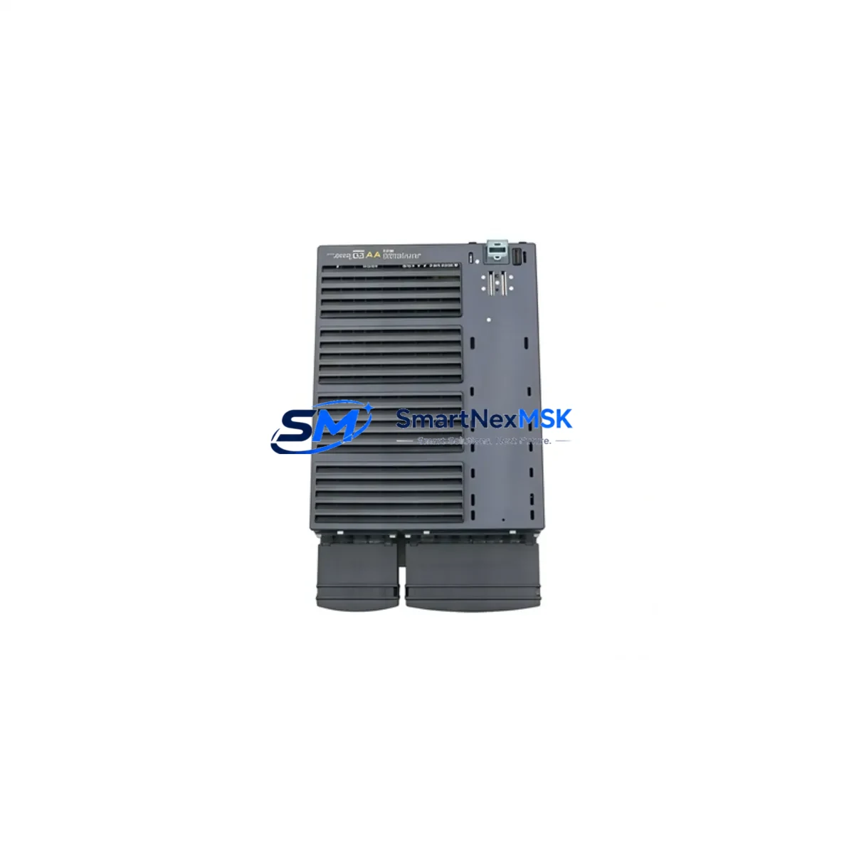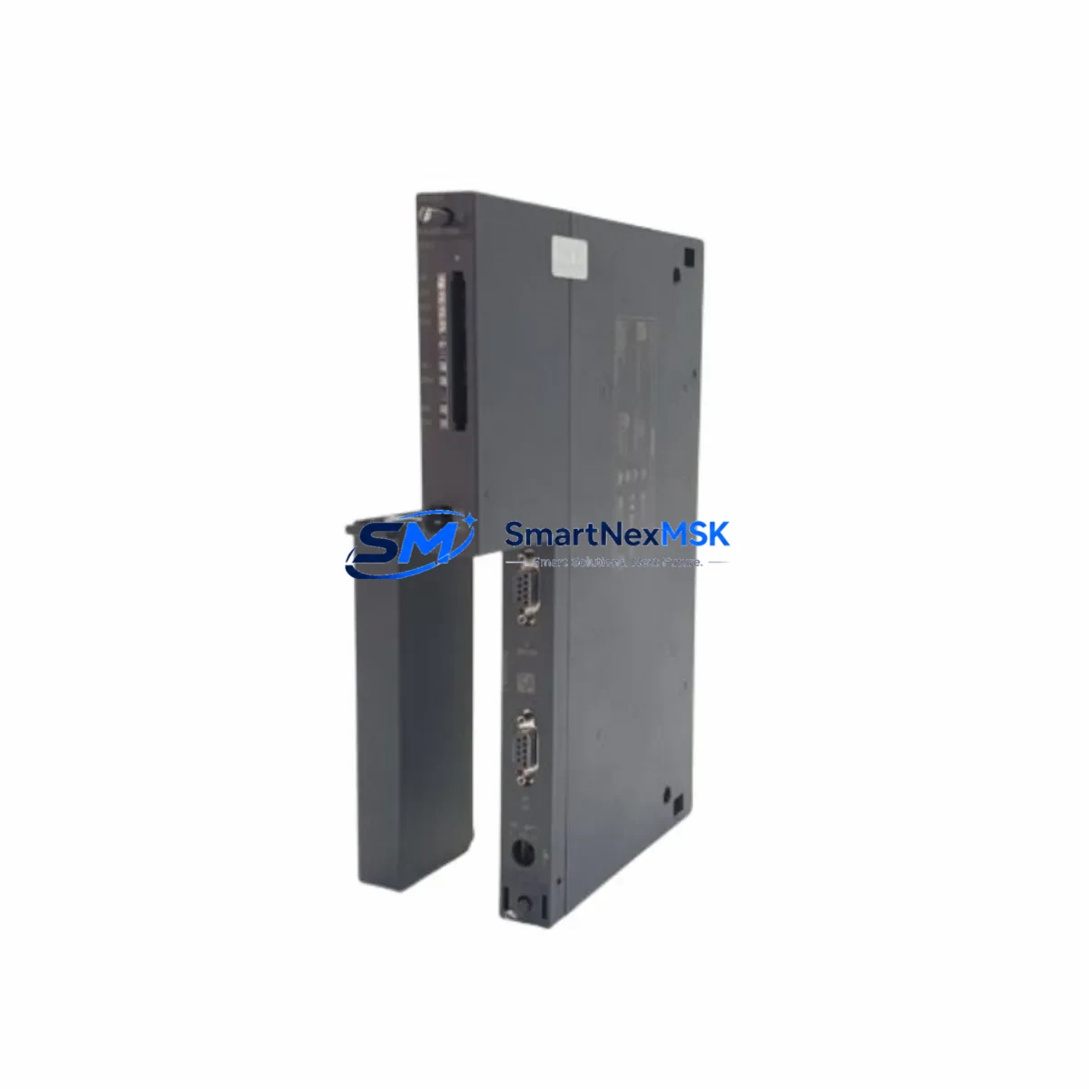
Siemens 6ES7416-2XP07-0AB0 Spare for S7-400 Automation: Downtime-Controlled CPU Replacement
The Siemens 6ES7416-2XP07-0AB0 is the CPU 416-2 central processing unit for the SIMATIC S7-400 programmable logic controller platform — one of the most widely deployed process automation architectures in heavy industry, power generation, chemical processing, and discrete manufacturing. When this CPU fails or reaches end-of-service life, the entire control rack goes offline. Holding a verified, tested spare on-site is the single most effective strategy for minimizing unplanned downtime and protecting production continuity.
At SMARTNEXMSK, every unit of the 6ES7416-2XP07-0AB0 is sourced from authorized supply chains, inspected against Siemens factory specifications, and function-tested prior to shipment. Each spare ships with a 12-month warranty, full documentation, and traceability records — giving maintenance engineers and procurement teams the confidence to stock this module as a long-term, lifecycle-managed spare.
Spare Maintenance Table
| Parameter | Specification |
|---|---|
| Part Number / SKU | 6ES7416-2XP07-0AB0 |
| Product Family | SIMATIC S7-400 |
| Module Type | CPU 416-2 Central Processing Unit |
| Working Memory | 5.6 MB (2.8 MB code / 2.8 MB data) |
| Communication Interfaces | MPI/DP (integrated), 2× PROFIBUS DP master/slave |
| Backplane Bus | S7-400 standard rack (UR1, UR2, ER1, ER2) |
| Supply Voltage | 24 V DC (via PS 407 / PS 405 power supply module) |
| Operating Temperature | 0 °C to +60 °C |
| Protection Class | IP20 |
| Country of Origin | Germany |
| Compatibility | SIMATIC S7-400 UR1/UR2/ER1/ER2 racks; STEP 7 V5.x / TIA Portal |
| Firmware | V7.0 (upgradeable via SIMATIC Micro Memory Card) |
| Condition | Original / New-equivalent, factory-tested |
| Warranty | 12 Months — SMARTNEXMSK Spare Parts Guarantee |
| Pre-shipment Test | Power-on, communication handshake, memory integrity check |
| Typical Replacement Scenario | CPU fault, memory corruption, PROFIBUS DP failure, planned lifecycle refresh |
Maintenance Planning for Continuous Operation
Replacing the 6ES7416-2XP07-0AB0 CPU is rarely an isolated event. A disciplined maintenance engineer treats a CPU swap as a trigger for a broader control-cabinet inspection. Before declaring the system restored, verify the condition and firmware revision of the PS 407 10A power supply module (6ES7407-0KA02-0AA0) — an aging or undersized power supply is a leading cause of CPU instability and false fault codes. Inspect the PS 405 4A backup power supply if the rack uses redundant power architecture.
Check all SM 321 digital input modules and SM 322 digital output modules seated in the same rack. A CPU fault event can mask latent I/O module failures; individual channel diagnostics should be re-run after the CPU is restored. Similarly, inspect any SM 331 analog input or SM 332 analog output modules for drift or calibration errors that may have accumulated during the fault period.
The CP 443-1 Ethernet communication processor and any installed CP 443-5 PROFIBUS communication modules should be checked for firmware compatibility with the replacement CPU firmware version. A mismatch between CPU firmware and CP module firmware is a common source of post-replacement communication faults that can delay restart by hours.
If the system uses a SIMATIC Micro Memory Card (MMC) for program storage, verify the card’s integrity and confirm the backup program image is current before inserting it into the replacement CPU. Stale or corrupted MMC data is a frequent cause of failed first-start after CPU replacement. For systems with IM 460 / IM 461 interface modules connecting expansion racks, inspect the inter-rack cables and connector pins — physical damage here can cause intermittent I/O faults that are difficult to diagnose after a CPU change.
Finally, review the UR2 rack backplane bus connector seating for all modules. Vibration in industrial environments can cause partial connector disengagement that only manifests as a fault after a CPU restart forces a full rack re-initialization.
Site Replacement Workflow
Step 1 — Pre-replacement backup: Using STEP 7 or TIA Portal, upload the current CPU program, hardware configuration, and diagnostic buffer to an engineering workstation. Confirm the Micro Memory Card backup is current.
Step 2 — Safe shutdown: Place the CPU in STOP mode. Confirm all controlled outputs are in a safe state. Notify process operators before de-energizing the rack.
Step 3 — Module extraction: De-energize the PS 407 power supply. Remove the 6ES7416-2XP07-0AB0 by releasing the front panel locking screws and sliding the module out of the rack slot. Note the slot position — the CPU must be reinstalled in the same slot (typically slot 4 in UR1/UR2 racks).
Step 4 — Replacement installation: Insert the replacement 6ES7416-2XP07-0AB0 into the same rack slot. Seat firmly until the backplane connector engages. Secure the front panel locking screws. Insert the Micro Memory Card with the verified program backup.
Step 5 — Power-on and verification: Re-energize the PS 407. Observe the CPU LED sequence — RUN/STOP and BUSF LEDs should clear within 30 seconds of a successful cold restart. Use STEP 7 or TIA Portal online diagnostics to confirm all I/O modules are recognized and no module faults are active.
Step 6 — Functional test: Run a controlled I/O test cycle before returning the system to automatic operation. Confirm PROFIBUS DP slave communication is established on both DP interfaces. Document the replacement in the site maintenance log with the new module serial number and firmware version.
This workflow is compatible with both hot-standby and single-CPU S7-400 configurations. For redundant CPU systems (S7-400H), follow the Siemens H-system switchover procedure to avoid process interruption during the replacement.
Spare Parts Support FAQ
Q1: Is the 6ES7416-2XP07-0AB0 still available as a new spare, or only as refurbished stock?
SMARTNEXMSK maintains stock of original and new-equivalent units sourced from authorized industrial supply channels. Each unit is inspected and tested before shipment. Refurbished units, when available, are clearly identified and priced separately. Contact sales@smartnexmsk.com to confirm current stock condition and lead time.
Q2: How do I verify compatibility with my existing S7-400 rack and software version?
The 6ES7416-2XP07-0AB0 (firmware V7.0) is compatible with all standard S7-400 UR1, UR2, ER1, and ER2 racks. It is supported by STEP 7 V5.4 SP5 and higher, and by TIA Portal V13 and higher with the S7-400 hardware support package. If your project was created with an earlier STEP 7 version, a hardware configuration update may be required before downloading to the replacement CPU. Our technical team can advise on firmware and software compatibility before you order.
Q3: What does the 12-month warranty cover, and what is the replacement process?
The 12-month SMARTNEXMSK spare parts warranty covers manufacturing defects, functional failure under normal operating conditions, and DOA (dead-on-arrival) units. It does not cover damage caused by incorrect installation, overvoltage, or environmental conditions outside the module’s rated specification. To initiate a warranty claim, contact sales@smartnexmsk.com with the order number, module serial number, and a description of the fault. Replacement units are dispatched within 3 business days of fault confirmation.
Q4: Can I order multiple units for a spare parts inventory program?
Yes. SMARTNEXMSK supports bulk spare parts procurement for planned maintenance programs, shutdown kits, and multi-site inventory strategies. Volume pricing is available for orders of 2 or more units. We can also provide long-term supply agreements with reserved stock allocation for customers managing large S7-400 installed bases. Contact our sales team to discuss your inventory requirements and lead-time commitments.
© 2026 SMARTNEXMSK. All rights reserved.
Original Source: https://smartnexmsk.com
Contact: sales@smartnexmsk.com | +86 18259474341