Siemens C98043-A7042-L1-6 Spare for SIMODRIVE Automation: Spare Replacement & Industrial Downtime Risk Control
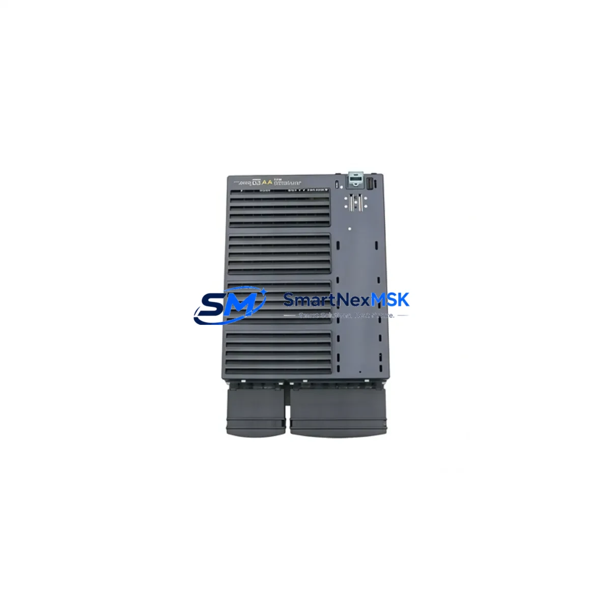
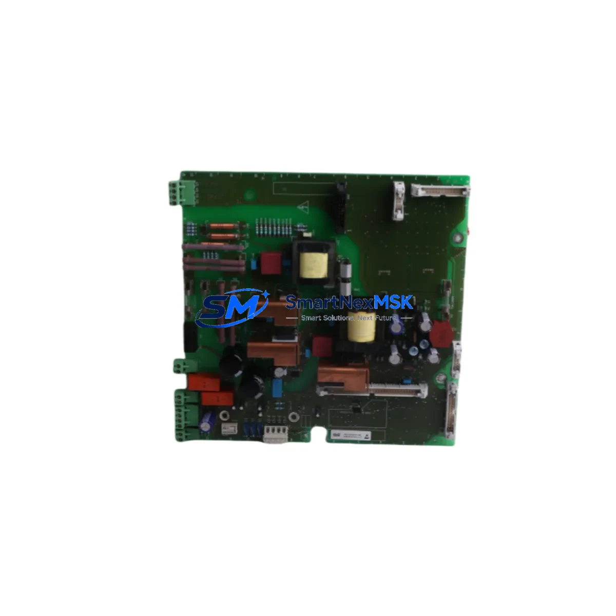
The Siemens C98043-A7042-L1-6 is an original Power Interface Board designed for use within the SIMODRIVE drive system platform — one of Siemens’ most widely deployed servo and spindle drive families in CNC machining, automated production lines, and precision motion control applications. As a critical interface component between the power section and the control electronics, this board governs DC bus regulation, gate signal distribution, and feedback signal conditioning. When this board fails, the entire drive axis goes offline, triggering unplanned downtime that can cascade across interconnected machine axes and production cells.
For maintenance engineers and spare parts procurement teams managing aging SIMODRIVE installations, stocking a verified replacement C98043-A7042-L1-6 is a fundamental risk mitigation strategy. This board is tested prior to dispatch, ships with a 12-month warranty, and is sourced to meet the original Siemens specification — ensuring drop-in compatibility without firmware reconfiguration or mechanical modification.
Spare Maintenance Table
| Parameter | Specification / Detail |
|---|---|
| Part Number | C98043-A7042-L1-6 |
| Description | Power Interface Board |
| Brand | Siemens |
| Compatible System | SIMODRIVE 611 / SIMODRIVE 611U / SIMODRIVE 611D |
| Function | DC bus interface, gate drive signal distribution, power feedback conditioning |
| Mounting | Direct board-level installation within SIMODRIVE power module |
| Input Voltage Range | Compatible with standard SIMODRIVE 3-phase AC input (per host module spec) |
| Operating Temperature | 0°C to +55°C (standard industrial cabinet environment) |
| Origin | Germany |
| Condition | Original spare — tested before dispatch |
| Warranty | 12 Months |
| Lead Time | In-stock items ship within 1–3 business days |
| Compatibility Verification | Cross-referenced against SIMODRIVE 611 hardware revision documentation |
| Maintenance Recommendation | Inspect DC bus capacitors and gate resistors during board replacement; clean connector contacts |
Maintenance Planning for Continuous Operation
Replacing the C98043-A7042-L1-6 in a live SIMODRIVE installation is rarely an isolated task. Experienced maintenance engineers treat a power interface board failure as a signal to audit the surrounding drive cabinet systematically. During the same maintenance window, it is advisable to inspect the SIMODRIVE 611 power supply module (e.g., 6SN1145 series) for signs of capacitor aging or thermal stress, as a degraded power supply can accelerate interface board failure through voltage ripple and transient spikes.
The drive control board (Regelungsbaugruppe) paired with this interface board — typically from the 6SN1118 or 6SN1121 series — should be checked for alarm history via the SINUMERIK CNC controller or SIMATIC S7 PLC diagnostic interface. Persistent axis alarms (e.g., F01 or F02 fault codes) prior to board failure often indicate that the control board has also been stressed. Replacing the interface board without verifying the control board’s integrity risks repeat failure within weeks.
Connector integrity is another critical checkpoint. The X131 and X141 terminal blocks on the SIMODRIVE power module should be inspected for oxidation, loose crimps, and thermal discoloration. Similarly, the 24V DC auxiliary power supply feeding the drive’s logic circuits should be load-tested — a sagging auxiliary supply is a common root cause of intermittent interface board faults that are misdiagnosed as board failures.
For sites running multi-axis SIMODRIVE configurations, the DC bus bar connections and bus capacitor modules shared across drive units deserve attention. A failed interface board in one axis can sometimes be traced to a bus capacitor imbalance affecting the entire drive group. Checking the regenerative feedback module (if installed) for correct operation ensures that braking energy is being handled properly and not stressing the interface boards of adjacent axes.
Communication integrity between the SIMODRIVE system and the host CNC or PLC should also be verified after board replacement. The PROFIBUS DP interface module or DRIVE-CLiQ connection (depending on system generation) should be re-initialized and tested for stable cyclic communication. If the machine uses a Siemens OP panel or HMI (such as the OP010 or OP015) for drive parameter access, confirm that drive parameters are correctly restored from backup after the replacement — parameter loss during a board swap is a common source of post-maintenance commissioning delays.
Finally, for older SIMODRIVE installations approaching end-of-life, it is prudent to stock not only the C98043-A7042-L1-6 but also the associated IGBT power module, current sensor board, and encoder interface module as a coordinated spare set. This approach minimizes the risk of a second unplanned outage caused by a related component failure discovered only after the primary repair is complete.
Site Replacement Workflow
Step 1 — Isolation & Safety: De-energize the SIMODRIVE cabinet following LOTO procedures. Discharge the DC bus (minimum 5-minute wait after power-off; verify with a calibrated voltmeter before touching internal components).
Step 2 — Documentation: Photograph the existing board orientation, connector positions, and any visible labeling before removal. Record the drive’s parameter set using the SINUMERIK or SIMATIC programming tool if not already backed up.
Step 3 — Board Removal: Disconnect all ribbon cables and terminal connectors from the C98043-A7042-L1-6 in sequence. Remove the board mounting screws and extract the board using ESD-safe handling procedures.
Step 4 — Inspection & Cleaning: Inspect the board slot for debris, corrosion, or burnt residue. Clean connector pins with isopropyl alcohol. Check the mating connectors on the power module chassis for damage.
Step 5 — Installation: Install the replacement C98043-A7042-L1-6, reconnect all cables in reverse order, and verify connector seating. Torque mounting screws to specification.
Step 6 — Commissioning: Re-energize the cabinet in stages. Monitor for alarm codes on the CNC/PLC display. Restore drive parameters from backup. Run a no-load axis test before returning the machine to production.
Step 7 — Documentation Closure: Update the maintenance log with the replacement date, part number, and post-replacement test results. Tag the removed board for failure analysis if required.
Spare Parts Support FAQ
Q1: Is the C98043-A7042-L1-6 compatible with all SIMODRIVE 611 variants?
The C98043-A7042-L1-6 is designed for specific hardware revisions within the SIMODRIVE 611 power module family. Compatibility depends on the host module’s hardware index (e.g., -L1, -L2 suffix variants). We recommend providing your full drive module part number and hardware revision when ordering to allow cross-reference verification before dispatch.
Q2: How is the board tested before shipment?
Each C98043-A7042-L1-6 unit undergoes functional testing covering gate signal output integrity, power rail continuity, and connector pin resistance checks prior to packaging. A test report is available upon request. All units ship with a 12-month warranty covering manufacturing defects and functional failure under normal operating conditions.
Q3: What is the recommended spare stock strategy for SIMODRIVE installations?
For facilities operating 3 or more SIMODRIVE axes, we recommend maintaining at least one C98043-A7042-L1-6 on-site as a critical spare. For larger installations or those in remote locations with extended lead times for emergency procurement, a two-unit buffer stock is advisable. Pairing this board with a spare control board and power supply module provides comprehensive coverage for the most common drive failure modes.
Q4: Can this board be used to extend the life of an end-of-life SIMODRIVE system?
Yes. The C98043-A7042-L1-6 is a direct replacement that restores the original drive functionality without requiring system-level upgrades or software changes. For facilities that have standardized on SIMODRIVE 611 and are not yet ready to migrate to SINAMICS, maintaining a stock of critical interface boards is a cost-effective strategy to extend system life by 5–10 years while a migration plan is developed.
© 2026 SMARTNEXMSK. All rights reserved.
Original Source: https://smartnexmsk.com
Contact: sales@smartnexmsk.com | +86 18259474341