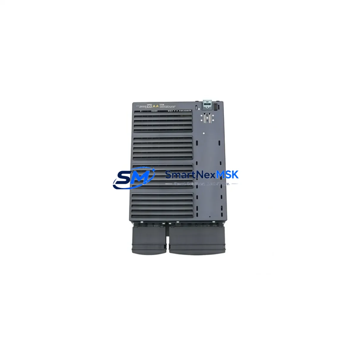
Siemens PS02-3005 Retrofit-Ready Interface Module for PS Series Control Systems
The Siemens PS02-3005 is a retrofit-ready interface module engineered for seamless integration into legacy PS Series control architectures. As industrial facilities face increasing pressure to modernize aging automation infrastructure without full system overhauls, the PS02-3005 delivers a proven migration path — enabling engineers to replace discontinued components, restore system integrity, and extend operational life with minimal disruption to existing wiring, backplane configurations, and control logic.
Whether you are replacing a failed unit on a running production line, upgrading a control cabinet as part of a phased modernization program, or sourcing a verified spare to protect against unplanned downtime, the PS02-3005 is stocked, tested, and ready to ship with a 12-month warranty.
Upgrade Compatibility Table
| Parameter | Details |
|---|---|
| Compatible Series | Siemens PS Series Control Systems |
| Module Type | Interface Module |
| Backplane Interface | PS Series standard backplane connector — direct slot replacement |
| Terminal Wiring | Matches original PS02-series terminal layout; no rewiring required in standard retrofit |
| Communication Compatibility | Compatible with PROFIBUS DP and MPI communication links used in PS Series platforms |
| Installation Requirement | DIN rail or rack-mount per PS Series cabinet standard; verify slot address assignment before power-on |
| Replacement Recommendation | Direct drop-in for discontinued PS02-series interface modules; confirm firmware revision compatibility with host CPU |
| Commissioning Notes | Re-assign module address in STEP 7 or TIA Portal; verify HMI tag mapping and I/O channel assignments post-swap |
| Warranty | 12 Months — covers manufacturing defects; includes pre-shipment functional test |
Retrofit Planning for Existing Automation Systems
Successful retrofit of the PS02-3005 into an existing PS Series control system requires a structured pre-migration assessment. Engineers should begin by auditing the current rack configuration — identifying the CPU module (such as a Siemens CPU 315-2 DP or CPU 317-2 PN/DP), the power supply module (typically a Siemens PS 307 series, rated at 5A or 10A depending on rack load), and all installed I/O modules occupying adjacent slots.
Before removing the legacy interface module, document the existing terminal block wiring using the original cabinet drawings. In many PS Series installations, the interface module connects to distributed I/O nodes via PROFIBUS DP cabling, and the bus termination resistors at each end of the segment must remain intact during the swap. If the system uses a Siemens IM 153-2 or IM 360/361 expansion interface for multi-rack configurations, verify that the new PS02-3005 module address does not conflict with existing rack assignments.
For systems incorporating Siemens ET 200M or ET 200S distributed I/O stations, confirm that the PROFIBUS DP segment scan cycle time remains within tolerance after the module replacement. Signal modules such as SM 321 digital input cards and SM 322 digital output cards should be re-verified in the hardware configuration tool to ensure channel mapping is preserved. Analog I/O modules — including SM 331 and SM 332 — require re-calibration checks if the interface module handles analog signal routing.
Power budget verification is critical: calculate the total current draw of all modules on the backplane and confirm the installed PS 307 power supply has sufficient headroom. If the retrofit is part of a broader control cabinet upgrade that includes adding new communication modules or expanding I/O capacity, a power supply upgrade may be required in parallel.
For facilities migrating from older STEP 7 Classic projects to TIA Portal, the PS02-3005 retrofit is an ideal checkpoint to re-validate the hardware configuration file, update the GSD file for any PROFIBUS devices, and confirm that the Siemens SIMATIC programming cable (PC Adapter USB or MPI/DP adapter) can establish a clean connection to the CPU after the module swap. HMI screens built on Siemens SIMATIC HMI TP700 or TP900 panels should be reviewed to confirm that any tags linked to the interface module’s I/O channels remain correctly mapped after the replacement.
Downtime Control During System Migration
Minimizing production downtime during a PS02-3005 module replacement requires careful pre-staging and a disciplined hot-swap protocol. Where the control system architecture permits, place the CPU in STOP mode only after coordinating with the production floor to identify a safe maintenance window. Before powering down the rack, use STEP 7 or TIA Portal to upload and archive the current program — including all data blocks, organization blocks, and function blocks — to a secure engineering workstation. This ensures that the original control logic can be restored immediately if any issue arises during commissioning of the replacement module.
Label all terminal connections on the interface module before disconnection, and photograph the wiring layout as a reference. If the PS Series rack uses a Siemens S7-300 backplane bus connector, inspect the connector pins for corrosion or mechanical damage before inserting the PS02-3005. After installation, power on the rack and monitor the CPU diagnostic buffer for any hardware fault entries. Re-download the hardware configuration to the CPU to register the new module, then switch the CPU to RUN mode and verify that all I/O signals are responding correctly before releasing the line back to production.
For critical processes where even brief interruptions are unacceptable, consider staging a parallel test rack with the PS02-3005 pre-configured and validated before the live swap. This approach — combined with pre-tested program archives and verified HMI tag mappings — can reduce total migration downtime to under 30 minutes in most PS Series retrofit scenarios.
Retrofit Support FAQ
Q1: Is the PS02-3005 a direct drop-in replacement for my existing PS Series interface module?
In most PS Series rack configurations, the PS02-3005 is a direct slot replacement. You should verify the backplane connector type, module address assignment, and firmware revision compatibility with your host CPU before installation. Our technical team can assist with compatibility confirmation based on your existing hardware configuration file.
Q2: What commissioning steps are required after installing the PS02-3005?
After physical installation, re-assign the module slot address in your STEP 7 or TIA Portal hardware configuration, download the updated configuration to the CPU, and verify all I/O channel assignments. Check the CPU diagnostic buffer for any fault entries and confirm that PROFIBUS DP communication links are re-established. HMI tag mappings linked to the module’s I/O channels should also be validated before returning the system to production.
Q3: Can the PS02-3005 be used in systems that have mixed PROFIBUS DP and MPI communication segments?
Yes. The PS02-3005 is compatible with PS Series systems using both PROFIBUS DP and MPI communication architectures. Ensure that bus termination is correctly configured at both ends of each segment and that the module address does not conflict with other nodes on the network. If you are migrating from MPI to PROFIBUS DP as part of a broader upgrade, our team can advise on segment configuration and GSD file updates.
Q4: What does the 12-month warranty cover, and is pre-shipment testing included?
Every PS02-3005 unit ships after a functional pre-shipment test covering power-on diagnostics, backplane interface verification, and communication link checks. The 12-month warranty covers manufacturing defects and functional failures under normal operating conditions. Warranty claims are processed directly through SMARTNEXMSK with a target response time of 48 hours. Replacement units are dispatched from stock to minimize your system downtime.
© 2026 SMARTNEXMSK. All rights reserved.
Original Source: https://smartnexmsk.com
Contact: sales@smartnexmsk.com | +86 18259474341