SMC INR-244-755 Retrofit-Ready Fieldbus Power Supply for EX Series Control Systems
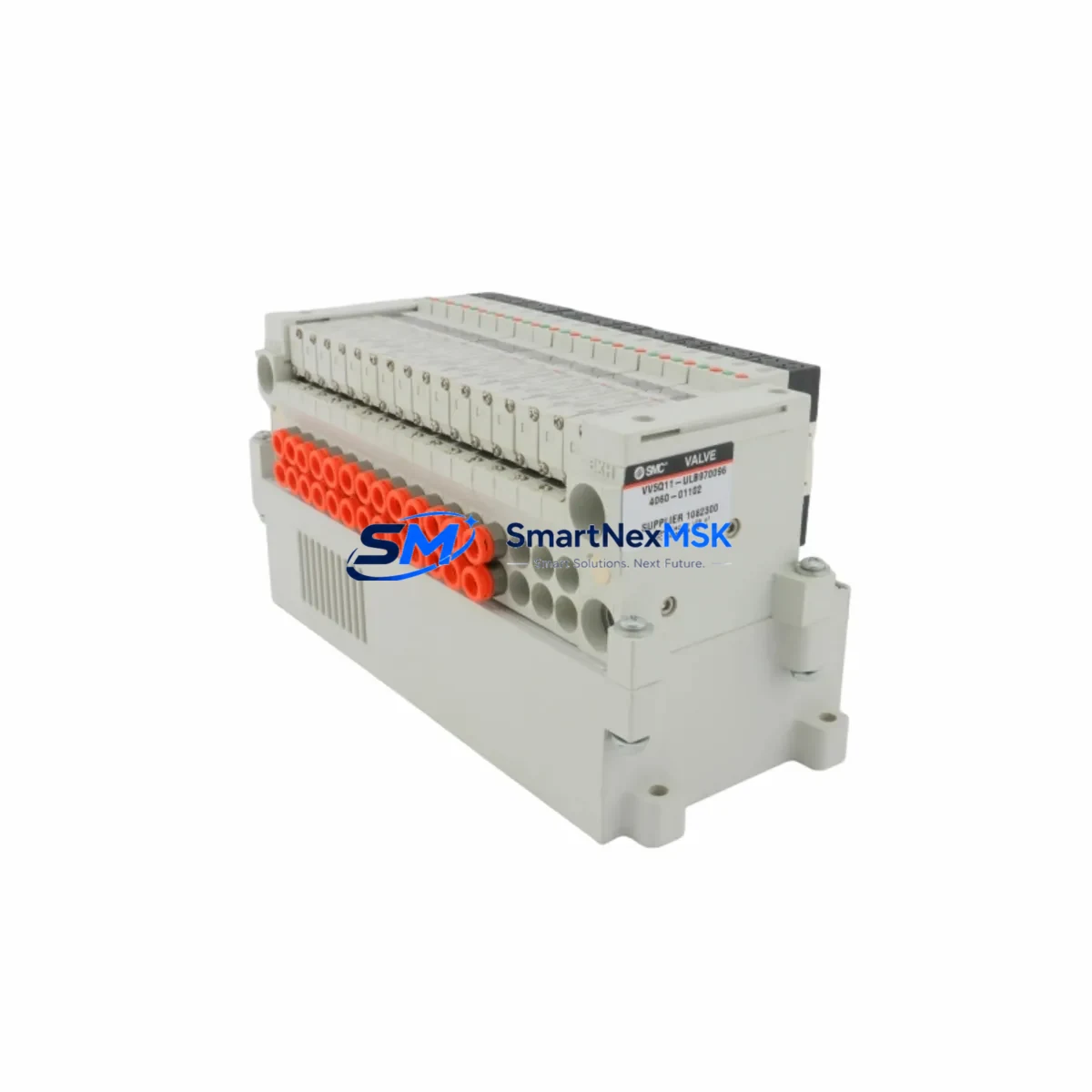
The SMC INR-244-755 is a dedicated fieldbus manifold power supply engineered for seamless integration into SMC EX Series pneumatic valve manifold systems. As legacy control architectures age and original power supply units reach end-of-life, the INR-244-755 provides a verified, drop-in retrofit path that preserves existing wiring layouts, terminal assignments, and fieldbus communication links — minimizing engineering rework and unplanned downtime during system migration.
Whether you are upgrading a DeviceNet-based valve island in an automotive assembly line, replacing a failed power unit in a food and beverage packaging system, or modernizing a distributed I/O cabinet in a semiconductor fab, the INR-244-755 delivers the electrical stability and protocol compatibility that EX Series manifolds demand. Its compact DIN rail form factor and standardized terminal block layout allow technicians to complete a like-for-like swap without modifying the control cabinet structure or re-routing field cables.
Upgrade Compatibility Table
| Parameter | Detail |
|---|---|
| SKU / Part Number | INR-244-755 |
| Brand / Manufacturer | SMC Corporation |
| Product Series | EX Series Fieldbus Manifold |
| Product Type | Fieldbus Manifold Power Supply |
| Mounting Style | DIN Rail / Manifold End Plate |
| Compatible Fieldbus Protocols | DeviceNet, CC-Link, PROFIBUS-DP (EX Series dependent) |
| Terminal Interface | Standard screw terminal block, compatible with existing EX Series wiring |
| Replacement Compatibility | Direct retrofit for SMC EX Series manifold power supply positions |
| Installation Requirement | Verify supply voltage, node address, and baud rate before installation |
| Commissioning Notes | Confirm manifold address settings and fieldbus master scan list after swap |
| Origin | Japan |
| Warranty | 12 Months — covers manufacturing defects and functional failure under normal use |
Retrofit Planning for Existing Automation Systems
A successful retrofit of the INR-244-755 into an existing EX Series installation begins well before the physical swap. Engineers should first audit the control cabinet to confirm the available 24 VDC supply capacity from the panel power supply — typically a Siemens SITOP PSU100S or Phoenix Contact QUINT-PS unit — ensuring sufficient current headroom for the manifold’s solenoid load plus the fieldbus communication circuit. Terminal block wiring should be photographed and documented against the original SMC EX600 or EX250 series manifold wiring diagram before any disconnection.
On the fieldbus side, the existing network topology must be reviewed. If the manifold is connected via a DeviceNet trunk using a Turck or Belden DeviceNet cable assembly, the node address configured on the outgoing INR-244-755 must match the address stored in the PLC’s I/O configuration — typically managed through a Rockwell Automation Studio 5000 or Siemens TIA Portal project. Changing the node address without updating the PLC scan list will result in a communication fault and prevent the manifold from responding to output commands.
For systems using CC-Link, the station number and transmission speed set on the SMC EX260 series gateway must be verified against the CC-Link master module — such as a Mitsubishi Electric QJ61BT11N — before powering up the replacement unit. Similarly, PROFIBUS-DP installations should confirm the GSD file version loaded in the engineering station matches the INR-244-755’s supported profile to avoid configuration mismatches.
Beyond the communication layer, technicians should inspect the manifold’s solenoid valve coils — such as SMC SY series or VQC series solenoids — for signs of coil degradation or short circuits that may have contributed to the original power supply failure. Replacing the INR-244-755 without addressing a downstream coil fault risks premature failure of the new unit. A quick insulation resistance check across the solenoid terminals before reconnection is strongly recommended.
If the retrofit involves migrating from an older EX120 or EX180 series manifold to a current EX600 platform, additional planning is required for the I/O mapping. The new manifold’s byte allocation in the PLC program may differ from the legacy configuration, requiring updates to the ladder logic or function block diagram. HMI screens built in Weintek, Proface, or Siemens SIMATIC HMI panels that display valve status indicators will also need tag remapping to reflect the new I/O addresses. Keeping a parallel test environment active during the migration — using a spare PLC CPU or offline simulation — allows engineers to validate the updated program before committing to a live cutover.
Downtime Control During System Migration
Minimizing production interruption during an INR-244-755 retrofit requires a structured cutover plan. The most effective approach is to pre-stage the replacement unit on a bench, pre-configure the node address and any DIP switch settings to match the outgoing module, and verify the unit powers up correctly with a bench 24 VDC supply before bringing it to the field. This eliminates configuration errors as a source of extended downtime during the live swap window.
On the day of cutover, the sequence should follow a defined lockout/tagout procedure: isolate the panel power supply feeding the manifold circuit, disconnect the fieldbus trunk connector and terminal block wiring from the old unit, install the INR-244-755, reconnect wiring in reverse order, and restore power. The entire physical swap typically takes under 15 minutes for a trained technician familiar with the EX Series manifold architecture.
After power restoration, the PLC should be placed in a controlled state — outputs inhibited — while the fieldbus master performs its network scan and confirms the manifold node is online. Only after the engineering station confirms a clean I/O status with no communication faults should the system be returned to automatic mode. Retaining the original program backup on a USB drive or in the version control system ensures that any unexpected behavior can be rolled back without delay. With proper pre-staging and a disciplined cutover sequence, total planned downtime for an INR-244-755 replacement can be held to under 30 minutes in most EX Series installations.
Retrofit Support FAQ
Q1: Is the INR-244-755 a direct drop-in replacement for the original SMC EX Series manifold power supply?
Yes. The INR-244-755 is designed as a compatible replacement for SMC EX Series fieldbus manifold power supply positions. The terminal block layout and mounting interface are consistent with the EX Series platform. Customers should confirm the specific manifold model and supply voltage requirements before ordering to ensure full compatibility with their installed configuration.
Q2: What pre-shipment testing is performed on the INR-244-755?
Each unit undergoes functional power-on verification and output voltage testing prior to dispatch. Units are inspected for physical integrity and packaged to prevent transit damage. A 12-month warranty covers manufacturing defects and functional failure under normal operating conditions from the date of shipment.
Q3: What information should I provide to confirm compatibility before ordering?
Please provide your existing manifold model number (e.g., EX600-DXP, EX250-SDN1), the fieldbus protocol in use (DeviceNet, CC-Link, or PROFIBUS-DP), and the supply voltage of your panel. This allows our technical team to confirm the INR-244-755 is the correct replacement and advise on any address or configuration steps specific to your installation.
Q4: What is the lead time and do you maintain stock?
The INR-244-755 is maintained in stock for immediate dispatch. Orders confirmed before the daily cut-off are typically shipped the same business day. For large-quantity requirements or long-term supply agreements, please contact our sales team to discuss scheduled delivery and pricing arrangements.
© 2026 SMARTNEXMSK. All rights reserved.
Original Source: https://smartnexmsk.com
Contact: sales@smartnexmsk.com | +86 18259474341