Sumitomo UMC554000-04 Retrofit-Ready AC Servo Driver for UMC Series Control Systems
The Sumitomo UMC554000-04 is a high-performance AC servo driver engineered for seamless integration into existing UMC Series automation architectures. As legacy servo systems age and original components reach end-of-life, the UMC554000-04 provides a verified retrofit path that preserves existing wiring layouts, program logic, and communication configurations — minimizing engineering rework and unplanned downtime during system modernization.
Designed for industrial environments where control continuity is critical, this unit supports direct replacement of discontinued UMC Series servo amplifiers without requiring full panel redesign. Engineers and maintenance teams working on aging production lines, packaging machinery, CNC transfer systems, and material handling equipment will find the UMC554000-04 a reliable, specification-matched solution for restoring or upgrading servo axis performance.
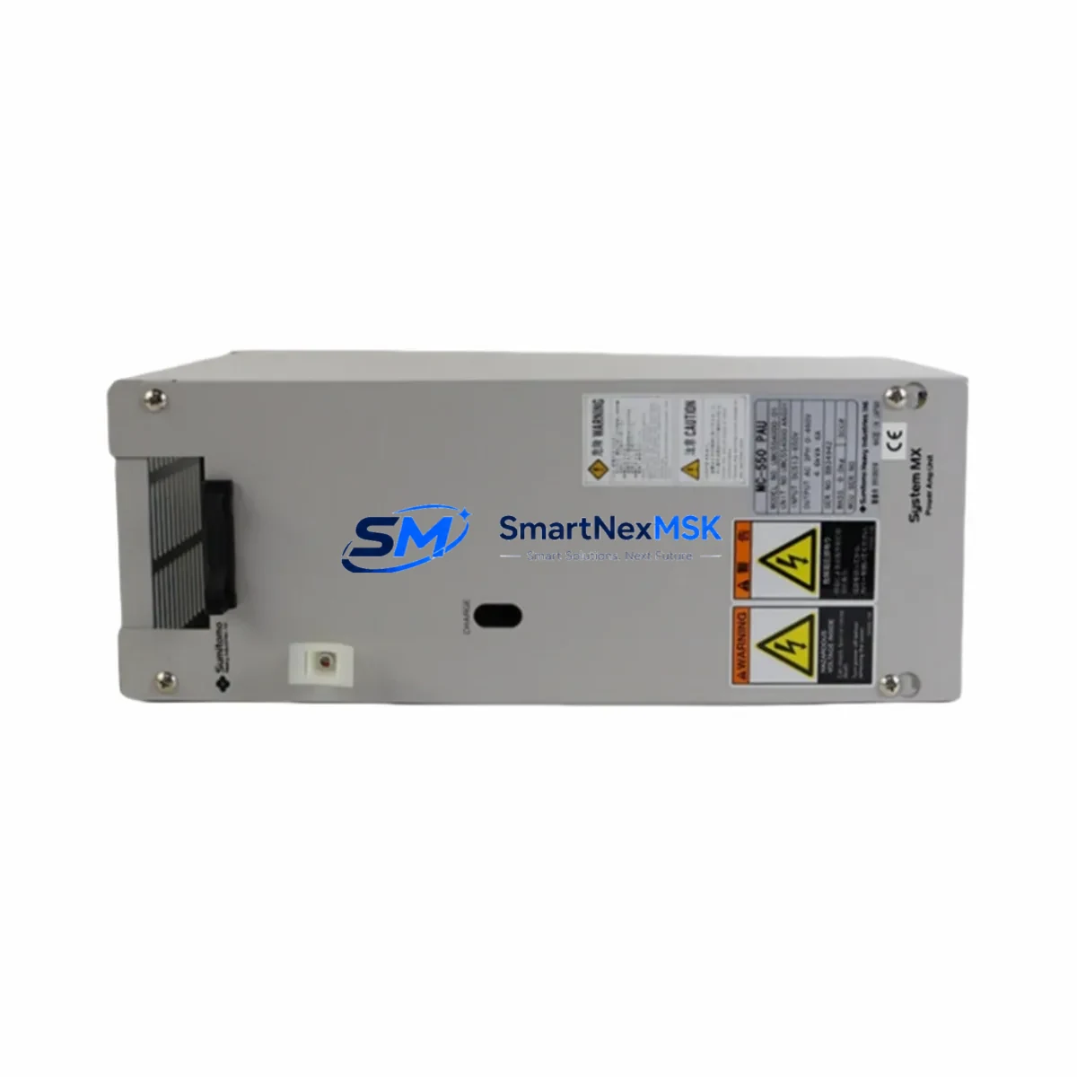
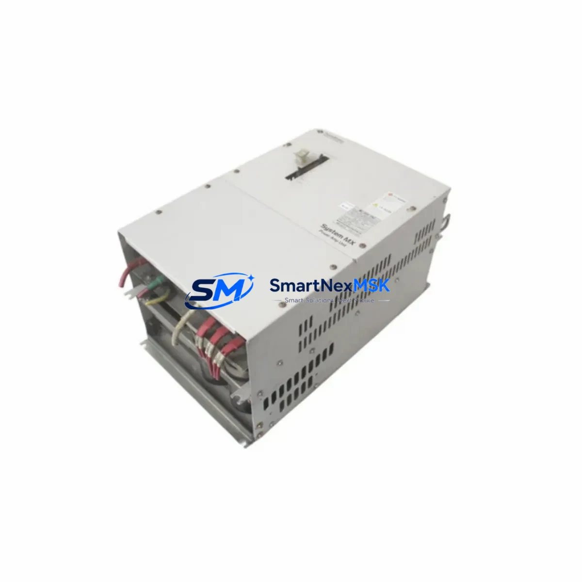
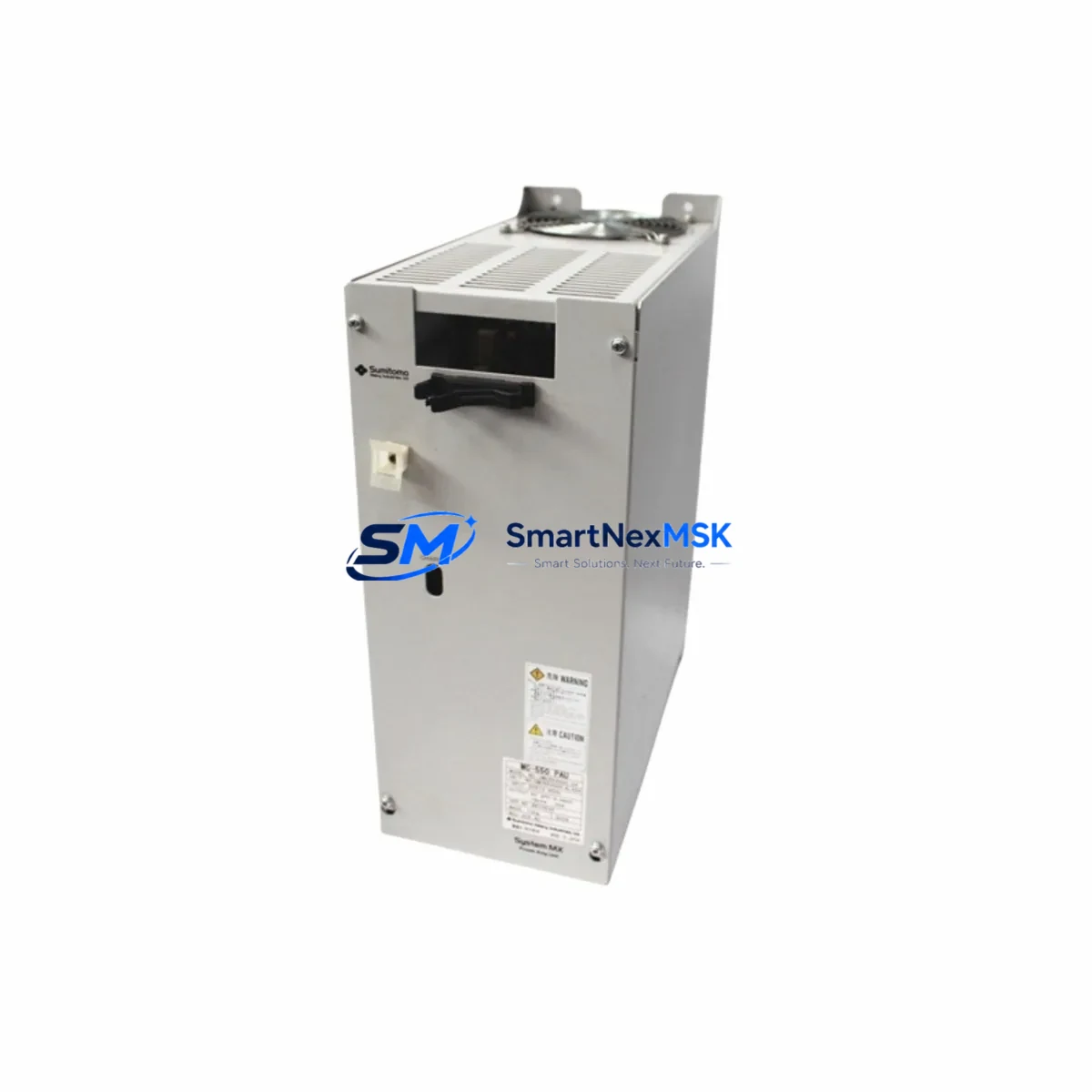
Before installation, technicians should verify the power supply capacity at the control cabinet level. The UMC554000-04 draws from the same DC bus architecture as its predecessors, but aging power supply modules — particularly Sumitomo UMC-series DC bus units — may require inspection or replacement if they have been in continuous service for more than five years. Confirming that the power supply module can sustain rated output under full servo load is a prerequisite for stable operation post-retrofit.
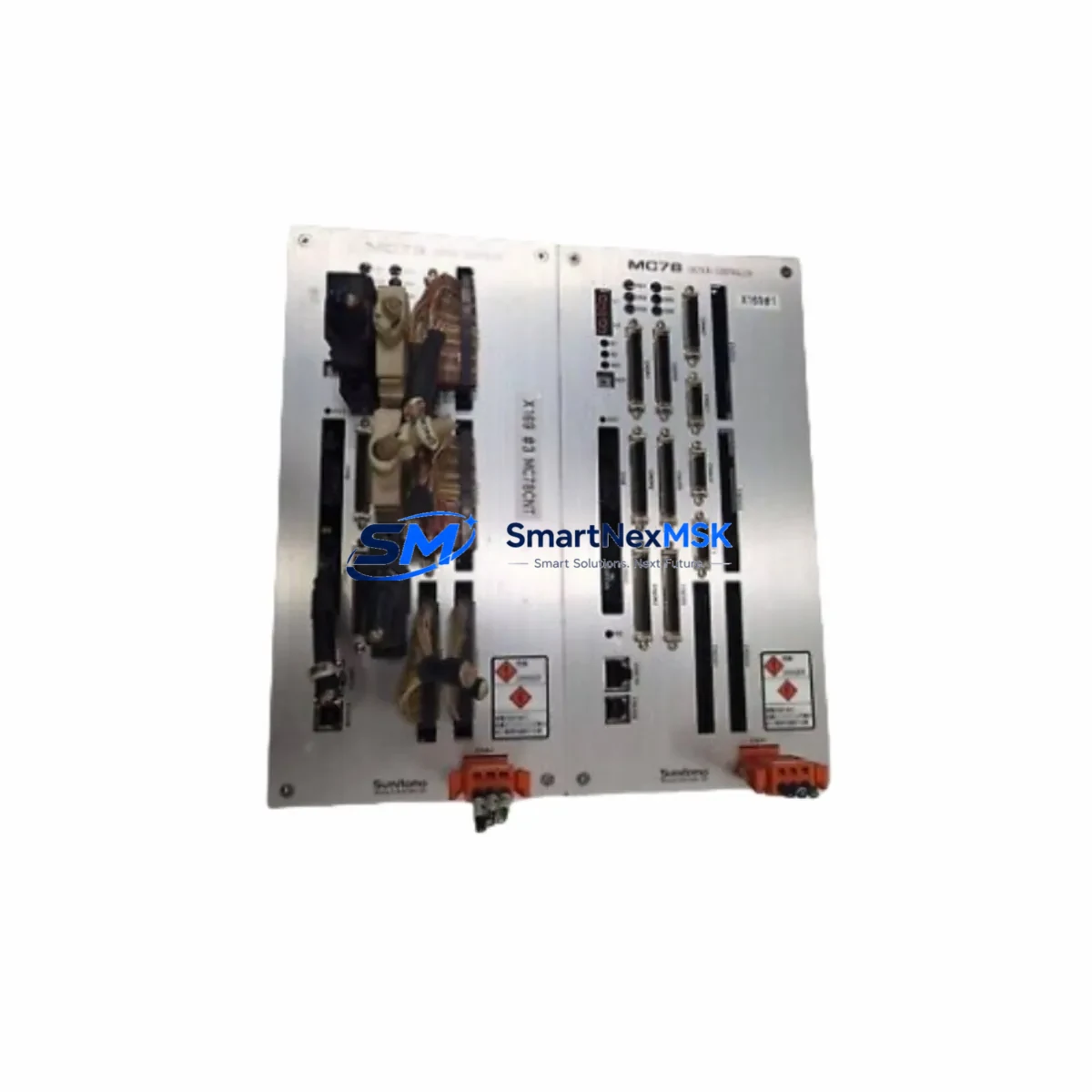
Terminal wiring compatibility is a key advantage of this unit. The UMC554000-04 retains the standard CN1 and CN2 connector pinout used across the UMC Series family, allowing existing motor feedback cables and I/O signal harnesses to be reconnected without modification. However, technicians should inspect the encoder cable shielding and verify that the motor feedback connector — typically a 15-pin D-sub or equivalent — is in serviceable condition before powering up the replacement unit.
Backplane and rack interface compatibility should be confirmed against the existing control cabinet layout. In multi-axis configurations, the UMC554000-04 shares the same rack slot dimensions as earlier UMC Series amplifiers, making it compatible with standard Sumitomo servo rack assemblies. When replacing a unit in a shared DC bus configuration, it is important to isolate the affected axis, discharge the bus capacitors, and follow the manufacturer’s lockout/tagout procedure before removing the failed module.
Module address configuration is handled via the front-panel DIP switch or rotary selector, consistent with the UMC Series addressing scheme. In multi-axis systems where the servo controller — such as a Sumitomo UMC Series motion controller or a compatible third-party PLC — polls each axis by node address, the replacement unit must be assigned the same address as the original to avoid communication faults and axis mapping errors in the control program.
Program compatibility is a critical consideration in any servo retrofit. The UMC554000-04 is parameter-compatible with the UMC Series servo tuning structure, meaning that gain settings, acceleration/deceleration ramps, torque limits, and electronic gear ratios from the original unit can be transferred directly using the Sumitomo servo setup software or a compatible handheld programmer. Technicians should back up the original parameter set before removal and restore it to the replacement unit prior to commissioning.
HMI screen updates are typically not required when performing a like-for-like UMC554000-04 replacement, as the axis status tags, alarm codes, and speed/torque feedback registers remain consistent across the UMC Series. However, if the HMI — whether a Sumitomo panel or a third-party operator interface — displays firmware version information or drive model identifiers, a minor screen revision may be needed to reflect the updated unit.
Communication link integrity should be verified after installation. The UMC554000-04 supports the serial communication protocols standard to the UMC Series, including RS-422 and RS-485 interfaces used for multi-drop servo network configurations. In systems where the servo network is supervised by a host PLC or motion coordinator, the communication cable routing, termination resistors, and baud rate settings should be confirmed to match the original configuration. If the existing communication module or interface card in the host controller is also aging, this retrofit presents an opportunity to inspect and replace those components concurrently.
I/O expansion compatibility is maintained through the standard digital I/O interface of the UMC554000-04, which supports the same input/output signal assignments as the replaced unit. In applications where external I/O modules — such as Sumitomo UMC Series I/O expansion units or third-party terminal blocks — are wired to the servo driver’s I/O connector, the signal mapping should be verified against the original wiring diagram before energizing the system.
Field commissioning of the UMC554000-04 follows the standard UMC Series startup sequence: power-on self-test, parameter verification, JOG operation at reduced speed, and full-cycle test under load. Technicians should monitor the DC bus voltage, motor current draw, and encoder feedback signal quality during initial operation. Any alarm codes generated during startup should be cross-referenced with the UMC Series alarm code table to identify root causes before proceeding to full production speed.
All units are pre-tested prior to shipment, covered by a 12-month warranty, and supported by in-stock availability for fast dispatch. SMARTNEXMSK maintains inventory of the UMC554000-04 and related UMC Series components to support urgent retrofit and breakdown recovery requirements.
Upgrade Compatibility Table
| Parameter | Details |
|---|---|
| SKU / Model | UMC554000-04 |
| Brand / Manufacturer | Sumitomo |
| Series | UMC Series |
| Product Type | AC Servo Driver / Servo Amplifier |
| Origin | Japan |
| Connector Interface | CN1 / CN2 compatible with UMC Series standard pinout |
| Communication Protocol | RS-422 / RS-485 (UMC Series serial network) |
| Rack / Backplane Fit | Compatible with standard Sumitomo UMC Series servo rack |
| Module Address Config | DIP switch / rotary selector (same as original UMC Series) |
| Parameter Transfer | Compatible with Sumitomo servo setup software and handheld programmer |
| Replacement Suitability | Direct drop-in for discontinued UMC Series servo amplifiers |
| Installation Requirement | Verify DC bus power capacity; inspect encoder cable and I/O harness |
| Commissioning Steps | Power-on self-test → parameter restore → JOG test → full-load trial |
| Warranty | 12 months from date of shipment |
| Stock Status | In Stock — available for immediate dispatch |
Retrofit Planning for Existing Automation Systems
A successful UMC554000-04 retrofit begins with a thorough audit of the existing control cabinet. In a typical UMC Series installation, the servo driver operates alongside a Sumitomo UMC Series motion controller or a compatible host PLC, sharing a common DC bus supplied by a dedicated servo power supply module. Before ordering the replacement unit, maintenance engineers should document the existing wiring layout, photograph the terminal block connections, and record the current parameter set from the original driver using the Sumitomo servo programmer or PC-based setup tool.
In multi-axis systems, the UMC554000-04 is commonly installed alongside other UMC Series servo drivers handling adjacent machine axes — for example, a feed axis driver, a clamp axis driver, and a rotary index axis driver may all share the same rack and DC bus. Replacing one axis driver while the others remain in service requires careful isolation to avoid disrupting the shared bus voltage. A Sumitomo UMC Series regenerative resistor unit or braking resistor module may also be present in the cabinet and should be inspected for condition during the retrofit.
The host controller’s I/O interface — whether a dedicated Sumitomo motion control card, a third-party PLC digital output module, or a pulse-train command interface — must be verified for signal compatibility with the UMC554000-04. In systems using a serial communication link, the communication cable connecting the host controller to the servo network should be tested for continuity and shielding integrity. A Sumitomo UMC Series communication interface module or RS-485 repeater may be present in larger multi-drop configurations and should be included in the pre-retrofit inspection checklist.
For systems where the original servo driver is connected to a Sumitomo or third-party HMI via an operator panel interface, the alarm display logic and axis status screens should be reviewed to confirm that the UMC554000-04’s alarm code structure is consistent with the existing HMI configuration. In most UMC Series installations, this is a direct match, but any custom alarm mapping in the HMI project should be verified before returning the machine to production.
Technicians should also inspect the motor power cable, encoder feedback cable, and any external dynamic braking resistor wiring for insulation condition and connector integrity. In long-running installations, cable degradation at the motor end — particularly at the servo motor’s terminal box — is a common source of post-retrofit faults that can be mistakenly attributed to the replacement driver. A pre-commissioning insulation resistance test on the motor winding and cable is recommended as part of the retrofit procedure.
Downtime Control During System Migration
Minimizing production downtime during a UMC554000-04 retrofit requires advance preparation and a structured changeover procedure. The most effective approach is to pre-configure the replacement unit off-line before the scheduled maintenance window. Using the Sumitomo servo setup software, technicians can load the backed-up parameter file from the original driver into the UMC554000-04, verify all gain settings and I/O assignments, and confirm communication address configuration — all before the machine is taken out of service.
During the changeover window, the recommended sequence is: isolate the affected axis from the DC bus, discharge the bus capacitors per the UMC Series safety procedure, remove the failed or end-of-life driver, install the pre-configured UMC554000-04, reconnect the CN1 and CN2 connectors, restore DC bus power, and perform a controlled JOG test at reduced speed before returning the axis to automatic mode. This structured approach typically allows a single-axis replacement to be completed within a two-to-four hour maintenance window, depending on cabinet accessibility and wiring complexity.
To protect the original program logic in the host PLC or motion controller, technicians should ensure that the controller’s program is backed up to a laptop or programming device before beginning the retrofit. In Sumitomo UMC Series systems, the motion program — including axis positioning sequences, cam profiles, and interlock logic — resides in the host controller, not in the servo driver itself, so the program is not at risk during driver replacement. However, confirming this architecture before starting work prevents unnecessary concern and ensures that the backup procedure is applied to the correct device.
Field control continuity can be maintained during a phased retrofit by keeping non-affected axes in service while the replacement axis is being commissioned. In multi-axis systems, the host controller’s axis enable logic should be reviewed to confirm that disabling one axis does not trigger a system-wide fault or emergency stop condition. If necessary, a temporary bypass or axis-disable parameter in the motion program can be used to allow the remaining axes to continue operating during the single-axis retrofit.
Retrofit Support FAQ
Q: Is the UMC554000-04 a direct replacement for all UMC Series servo drivers?
A: The UMC554000-04 is designed as a retrofit-compatible replacement for UMC Series servo amplifiers of equivalent power rating and interface configuration. Before ordering, confirm the original unit’s power rating, connector type, and communication protocol against the UMC554000-04 specification sheet. For mixed-series or cross-generation replacements, contact our technical team for compatibility verification.
Q: Can I transfer parameters from the original driver to the UMC554000-04?
A: Yes. The UMC554000-04 uses the same parameter structure as the UMC Series, and parameters can be transferred using the Sumitomo servo setup software or a compatible handheld programmer. Back up the original parameter set before removal and restore it to the replacement unit before commissioning. Verify all gain, limit, and communication settings after transfer.
Q: What wiring changes are required during installation?
A: In most UMC Series retrofit applications, no wiring changes are required. The UMC554000-04 retains the standard CN1 and CN2 connector pinout, allowing existing motor feedback cables and I/O signal harnesses to be reconnected directly. Inspect all connectors and cables for condition before reconnection. If the existing wiring does not match the UMC554000-04 connector layout, contact our support team for a wiring adaptation guide.
Q: What does the 12-month warranty cover?
A: All UMC554000-04 units supplied by SMARTNEXMSK are covered by a 12-month warranty from the date of shipment. The warranty covers manufacturing defects and component failures under normal operating conditions. Units are pre-tested prior to dispatch. Warranty claims should be submitted to sales@smartnexmsk.com with the order reference and a description of the fault. Out-of-warranty repair and exchange services are also available.
© 2026 SMARTNEXMSK. All rights reserved.
Original Source: https://smartnexmsk.com
Contact: sales@smartnexmsk.com | +86 18259474341