SUMITOMO UMC554000-07 Retrofit-Ready AC Servo Amp UMC
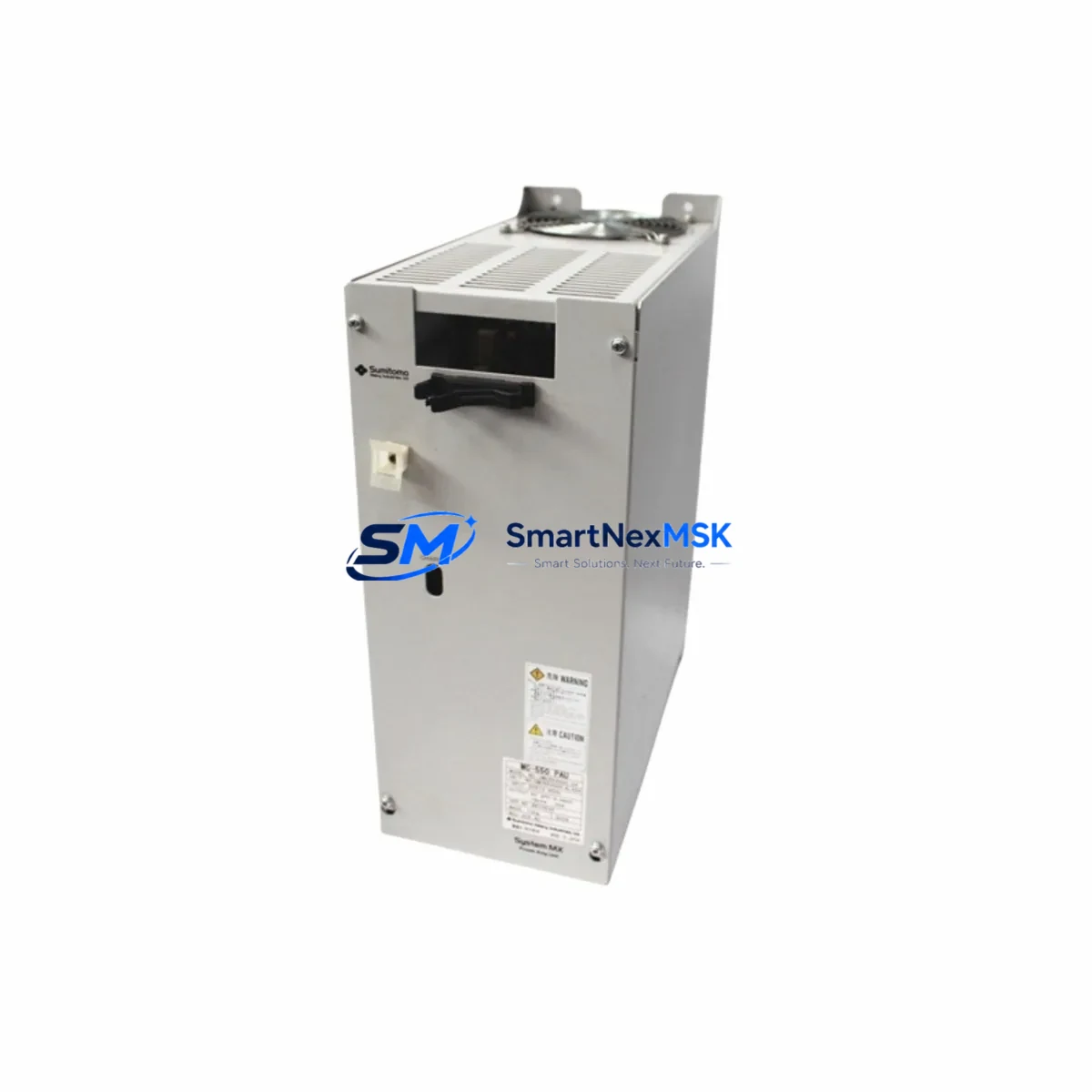
The SUMITOMO UMC554000-07 is a high-performance AC servo amplifier engineered for the UMC Series control platform. As legacy servo drive systems age and original units reach end-of-life, the UMC554000-07 provides a proven retrofit path that preserves existing wiring infrastructure, program logic, and mechanical interfaces — minimizing downtime and capital expenditure during system modernization.
For maintenance engineers managing aging production lines, the UMC554000-07 delivers a direct compatibility profile with the UMC Series servo controller architecture. Its terminal layout, feedback interface, and communication protocol alignment allow field technicians to execute a controlled swap without requiring full re-commissioning of the servo axis. This is particularly critical in continuous-process environments where unplanned downtime carries significant operational cost.
Procurement engineers sourcing this unit benefit from a verified supply chain, pre-shipment functional testing, and a 12-month warranty covering both component integrity and operational performance. Each unit is inspected against original SUMITOMO factory specifications before dispatch, ensuring that the replacement arrives ready for immediate installation.
Upgrade Compatibility Table
| Parameter | Specification |
|---|---|
| Model | UMC554000-07 |
| Brand | SUMITOMO |
| Series | UMC Series |
| Type | AC Servo Amplifier |
| Origin | Japan |
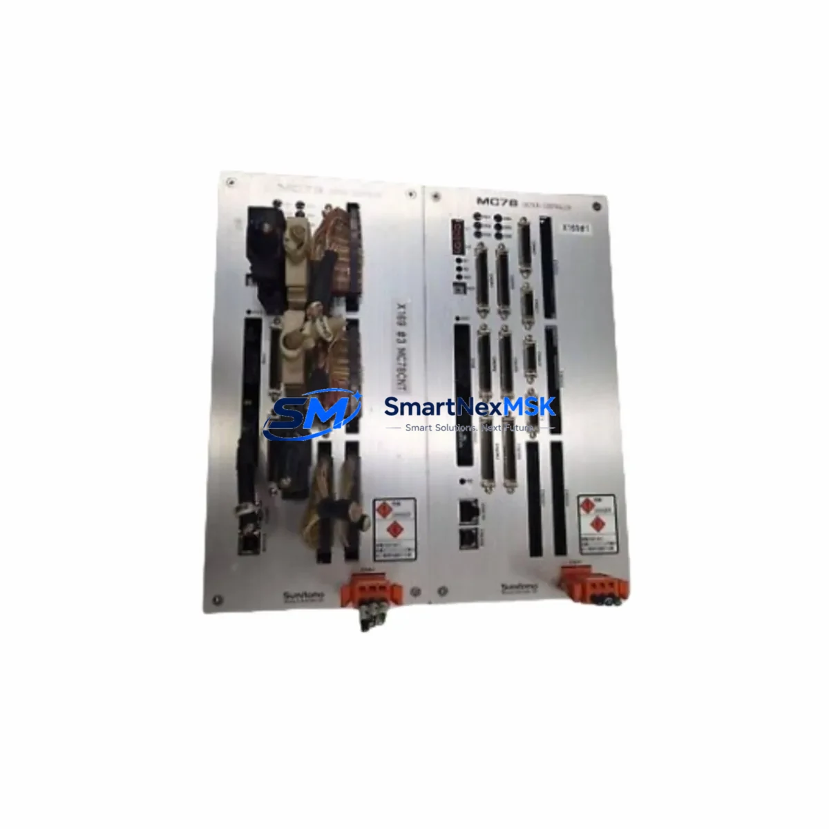
| Interface Compatibility | UMC Series servo controller backplane and terminal block |
| Communication Protocol | Compatible with UMC Series serial/encoder feedback bus |
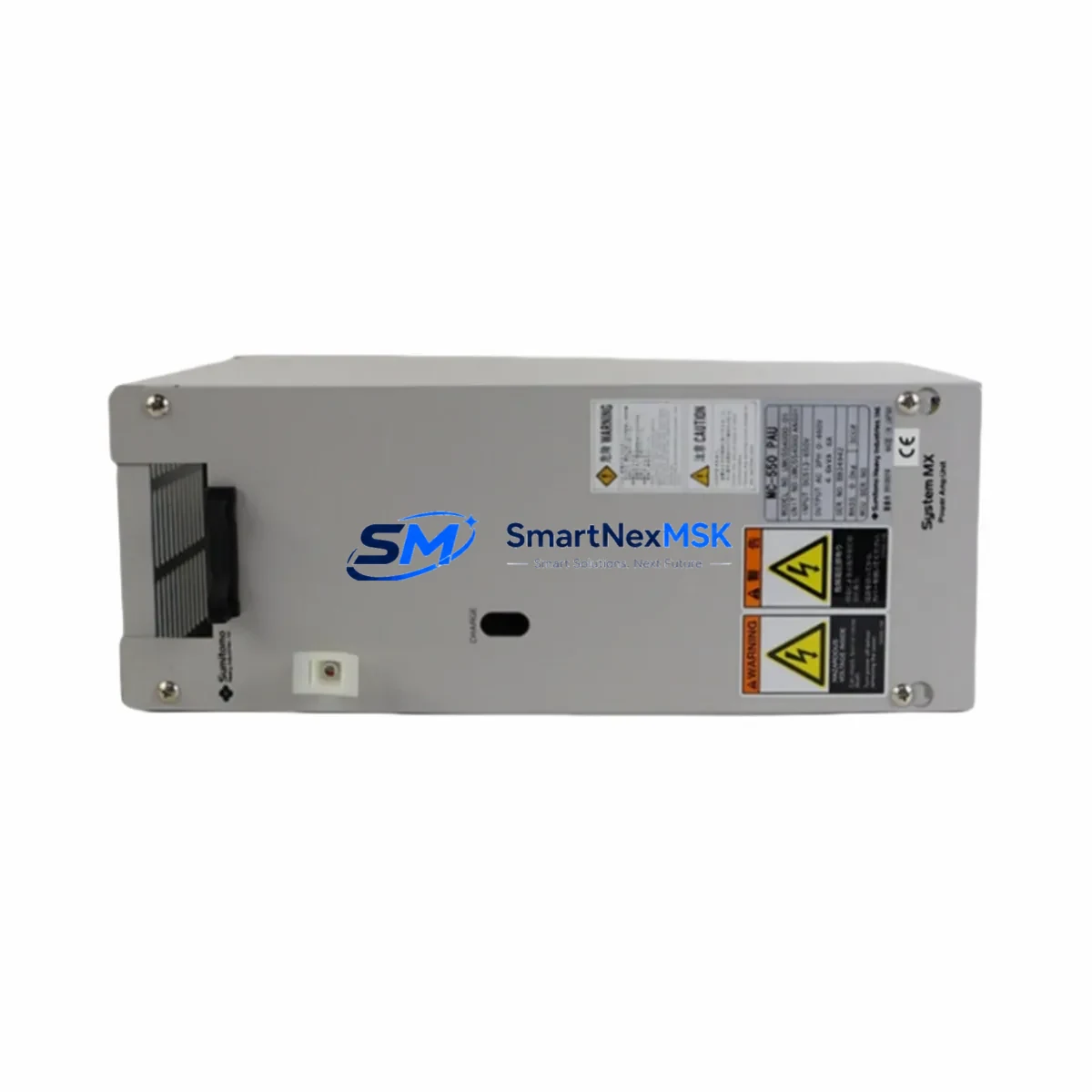
| Power Supply Requirement | Verify input voltage (AC 200V/400V class) before installation |
| Mounting | DIN rail / panel mount per original UMC Series specification |
| Replacement Scope | Direct drop-in for discontinued UMC554000-07 units |
| Commissioning Note | Confirm axis address, gain parameters, and encoder resolution |
| Warranty | 12 Months |
Retrofit Planning for Existing Automation Systems
A successful UMC554000-07 retrofit begins well before the unit arrives on site. Maintenance planners should audit the full servo axis assembly, starting with the UMC Series servo controller module that issues position and velocity commands. Confirm that the controller firmware version supports the amplifier’s feedback protocol — mismatched firmware revisions are a common source of commissioning delays in legacy system upgrades.
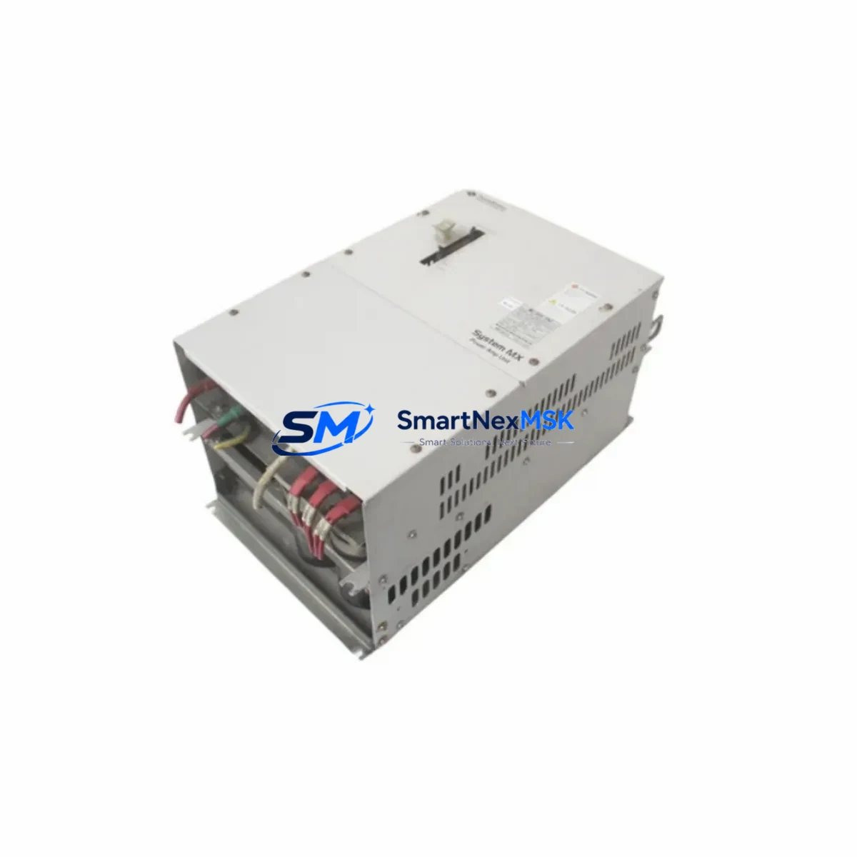
The power supply feeding the amplifier bus must be verified for adequate current capacity. In multi-axis cabinets, a shared DC bus power module or regenerative braking resistor unit may need inspection or replacement alongside the amplifier. Terminal block wiring — including motor power leads, encoder cable, and brake control lines — should be documented and photographed before disconnection to ensure accurate reconnection.
If the control cabinet includes a SUMITOMO UMC Series I/O expansion module or digital input/output terminal unit, verify that the axis enable signal, alarm reset line, and servo-ready interlock are correctly mapped in the PLC program. In systems where a MELSEC or SIMATIC PLC manages the motion sequence, the servo amplifier’s parameter file should be backed up from the existing unit using the manufacturer’s setup software before removal.
HMI screens displaying axis status, torque feedback, or fault codes should be reviewed to confirm that register addresses remain consistent after the swap. In older installations, the HMI may communicate with the servo amplifier via RS-232 or RS-485 — ensure the communication cable and port settings are preserved. Where a PROFIBUS DP or DeviceNet communication module is present in the cabinet, re-verify the node address assignment after installation.
Signal isolators on analog speed reference or torque limit inputs should be checked for drift, as aging isolation components can introduce offset errors that appear as servo tuning problems after a unit replacement. Fuse holders and circuit breakers on the amplifier input circuit should also be inspected and replaced if showing signs of thermal stress.
Downtime Control During System Migration
Controlled downtime management is the defining factor in a successful UMC554000-07 field replacement. The recommended approach is to prepare a complete replacement kit — including the amplifier, encoder cable, terminal ferrules, and parameter backup file — before scheduling the maintenance window. This eliminates the most common cause of extended downtime: discovering missing components after the original unit has been removed.
During the swap, retain the original motor cable and encoder harness if they are within service life. Re-using verified cables eliminates a variable from the commissioning process and reduces the risk of introducing wiring faults. After mechanical installation, restore the parameter file to the new amplifier before powering the axis, then perform a low-speed jog test to confirm encoder feedback direction and gain response before returning the axis to automatic mode.
For systems where the servo axis is part of a synchronized multi-axis sequence, coordinate the restart sequence with the PLC program logic to avoid position reference errors on adjacent axes. Document the completed replacement in the equipment maintenance log, including the new unit serial number, parameter file version, and commissioning date, to support future maintenance planning and warranty tracking.
Retrofit Support FAQ
Q: Is the UMC554000-07 a direct replacement for the original discontinued unit?
A: Yes. The UMC554000-07 is supplied as a direct form-fit-function replacement for the original SUMITOMO UMC Series servo amplifier. Terminal layout, mounting dimensions, and communication interface are compatible with the original installation. Minor parameter adjustments may be required during commissioning to match the specific motor and load characteristics of your application.
Q: What pre-shipment testing is performed on each unit?
A: Every UMC554000-07 unit undergoes functional power-on testing and electrical parameter verification before dispatch. Units are inspected for output stage integrity, encoder interface continuity, and control power response. A test report is available upon request. The unit ships with a 12-month warranty covering manufacturing defects and operational failure under normal industrial use conditions.
Q: How do I verify wiring compatibility before installation?
A: Compare the terminal block layout of the replacement unit against the original wiring diagram for your UMC Series cabinet. Pay particular attention to the motor power terminals (U/V/W), encoder connector pinout, brake control relay output, and analog reference input. If the original wiring diagram is unavailable, our technical team can provide reference documentation based on the cabinet configuration and motor model.
Q: What is the warranty coverage and support process?
A: The UMC554000-07 carries a 12-month warranty from the date of shipment. Warranty coverage includes component failure under normal operating conditions, excluding damage caused by incorrect installation, overvoltage, or environmental factors outside the rated specification. For warranty claims or technical support during commissioning, contact our team directly — response is provided within one business day.
© 2026 SMARTNEXMSK. All rights reserved.
Original Source: https://smartnexmsk.com
Contact: sales@smartnexmsk.com | +86 18259474341