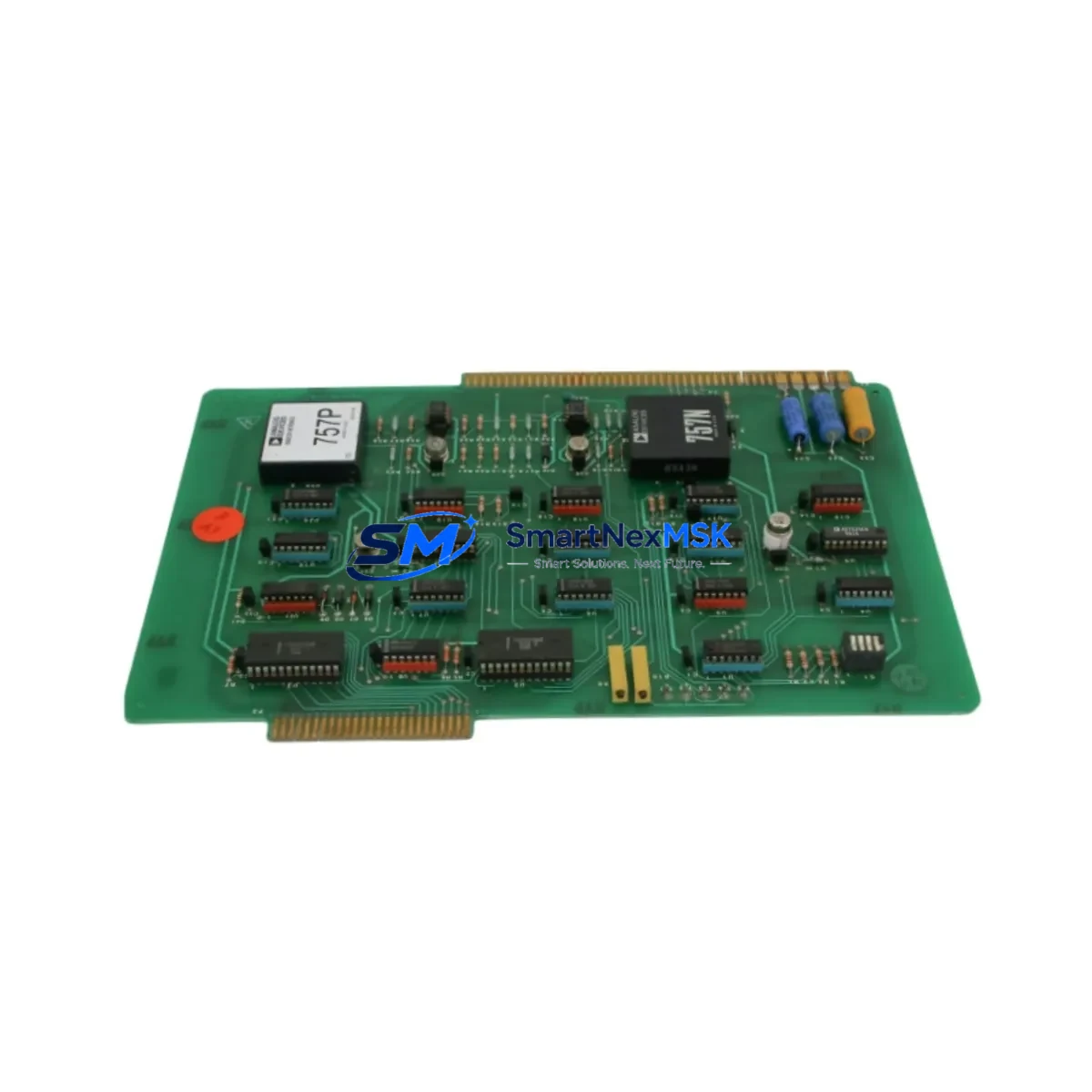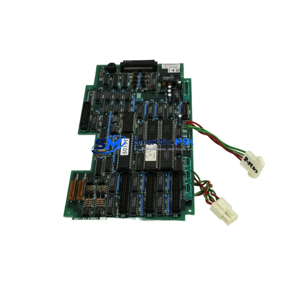
TEL 118100031717 MC-31035D Retrofit-Ready Control Panel for Y2O3 Process Control Systems
The TEL 118100031717 MC-31035D DIG 32-OK01 Y2O3 Retrofit-Ready Control Panel (SKU: 118100031717 MC-31035D DIG 32-OK01 Y2O3-TTELY2O3 KIT 030-001772) is a purpose-engineered replacement and upgrade solution for aging Tokyo Electron semiconductor process control systems. As legacy TEL platforms approach end-of-life and OEM support windows close, facilities engineering teams face mounting pressure to maintain uptime while sourcing compatible, tested replacement assemblies. This panel kit is designed to address exactly that challenge — providing a verified, retrofit-ready drop-in solution that preserves existing process logic, minimizes rewiring, and restores full system functionality without requiring a full platform migration.
Whether you are replacing a failed MC-31035D assembly in a Y2O3 etch or deposition system, upgrading a degraded DIG 32-OK01 interface board, or consolidating spare parts inventory ahead of a planned maintenance window, this kit delivers the compatibility and reliability your operation demands. Each unit is inspected, function-tested, and shipped with a 12-month warranty covering component integrity and operational performance.
Upgrade Compatibility Table
| Parameter | Details |
|---|---|
| Compatible Platform | Tokyo Electron (TEL) Y2O3 Process Control Systems |
| Replaces / Upgrades | MC-31035D DIG 32-OK01 Control Panel Assembly |
| Part Number | 118100031717 / 030-001772 |
| Interface Type | DIG 32-OK01 Digital I/O Interface |
| Backplane Compatibility | Compatible with standard TEL MC-series rack backplanes |
| Communication Protocol | Compatible with TEL proprietary serial and parallel control bus |
| Power Requirements | Verify existing cabinet PSU capacity before installation (typically 24VDC logic rail) |
| Installation Type | Panel-mount, direct retrofit into existing enclosure cutout |
| Wiring Adaptation | Terminal block layout matches legacy MC-31035D pinout; verify against as-built drawings |
| Commissioning Notes | Module address configuration required post-installation; confirm via TEL system parameter file |
| HMI Compatibility | Compatible with existing TEL operator interface screens; no HMI screen rebuild required in most cases |
| Warranty | 12 Months — covers component integrity and functional performance |
| Origin | CN |
| Shipping | In-stock units ship within 1–3 business days; export documentation available |
Retrofit Planning for Existing Automation Systems
Successful retrofit of the TEL 118100031717 MC-31035D panel begins well before the physical swap. Engineering teams should start by auditing the existing control cabinet layout, confirming the rack backplane slot assignments, and reviewing the current wiring schedule against the MC-31035D terminal block diagram. In many Y2O3 process tool installations, the control panel interfaces directly with a TEL MC-series power distribution module and one or more DIG 32-channel I/O expansion boards — both of which must be verified for compatibility before the new panel is seated.
Communication continuity is a critical checkpoint. The MC-31035D operates within a tightly coupled control architecture where the panel communicates with upstream recipe management software and downstream actuator controllers via the TEL proprietary control bus. Before disconnecting the legacy assembly, technicians should document all active node addresses, confirm the TEL system parameter configuration file is backed up, and verify that the replacement panel’s firmware revision is compatible with the installed recipe server version.
For facilities running mixed-generation equipment, it is common to find the Y2O3 control panel operating alongside legacy TEL EP-series endpoint detection modules, MFC (mass flow controller) interface cards, and RF match network controllers — all of which share the same control backplane or communicate over the same serial trunk. Confirming that the new MC-31035D panel does not conflict with existing node addressing on these modules is essential to avoiding communication faults at startup.
Wiring adaptation is typically straightforward when replacing like-for-like, but facilities that have undergone partial upgrades may find that terminal assignments have drifted from the original TEL schematic. In these cases, a point-to-point continuity check of all I/O connections — including digital inputs from pressure transducers, flow switches, and interlock relay modules — should be completed before powering the new panel. Pay particular attention to the 24VDC logic supply rail: confirm that the existing TEL cabinet power supply unit has sufficient current headroom to support the replacement panel without triggering overcurrent protection on shared rails.
If the retrofit is part of a broader control system upgrade that includes migrating from an older TEL TCS (Tool Control Software) version to a newer platform, additional steps are required to remap I/O tags, update HMI screen bindings, and validate alarm logic. In these scenarios, coordination with the process engineering team is recommended to ensure that the new panel’s digital output assignments align with the updated control narrative.
Downtime Control During System Migration
Minimizing unplanned downtime during a control panel retrofit requires a structured approach that protects both the original program logic and the physical integrity of the process tool. The recommended strategy is to treat the MC-31035D replacement as a hot-swap-equivalent procedure — even though it requires a controlled power-down — by completing all pre-work during scheduled maintenance windows and staging all materials in advance.
Begin by exporting a full backup of the TEL system parameter file and any custom recipe modifications stored on the tool controller. If the facility uses a TEL host computer interface or SECS/GEM communication layer, notify the MES team to place the tool in maintenance mode before disconnecting the panel to avoid spurious alarm events propagating to the fab-level monitoring system.
During the physical swap, label all disconnected wiring harnesses and document terminal positions with photographs before removal. Re-seat the new MC-31035D panel, reconnect all terminal blocks in sequence, and perform a cold-start power-up with all process gas and RF systems isolated. Verify that the panel initializes correctly, that all I/O channels report expected states, and that communication with the tool controller is established before releasing the tool for process qualification.
Post-installation, run a full I/O checkout sequence — cycling each digital output and confirming the corresponding input response — before executing a process qualification run. This structured commissioning approach typically allows a complete MC-31035D retrofit to be completed within a single 8-hour maintenance shift, keeping unplanned downtime to an absolute minimum and preserving full process continuity.
Retrofit Support FAQ
Q1: Is the TEL 118100031717 MC-31035D a direct drop-in replacement for the original assembly?
A: In the majority of Y2O3 process tool installations, yes. The MC-31035D DIG 32-OK01 panel is designed to match the original form factor, terminal block layout, and backplane connector pinout. However, facilities that have performed non-standard wiring modifications or firmware upgrades should verify compatibility against their as-built documentation before installation.
Q2: What commissioning steps are required after installing the replacement panel?
A: After physical installation and wiring reconnection, the module address must be confirmed or reconfigured via the TEL system parameter file. A full I/O checkout — verifying all 32 digital channels — should be completed before process qualification. If the tool uses SECS/GEM communication, confirm that the host interface re-establishes connection correctly after the panel restart.
Q3: Can this panel be used in systems that have been partially upgraded to newer TEL control platforms?
A: Yes, in most cases. The MC-31035D is compatible with mixed-generation TEL control architectures, provided that the backplane slot assignment and node addressing do not conflict with other installed modules. Consult your TEL system schematic and parameter file to confirm compatibility in hybrid configurations.
Q4: What does the 12-month warranty cover, and what is the shipping lead time?
A: The 12-month warranty covers component integrity and functional performance under normal operating conditions. In-stock units typically ship within 1–3 business days. Pre-shipment functional testing is performed on all units. Export documentation, including commercial invoice and packing list, is provided as standard.
© 2026 SMARTNEXMSK. All rights reserved.
Original Source: https://smartnexmsk.com
Contact: sales@smartnexmsk.com | +86 18259474341