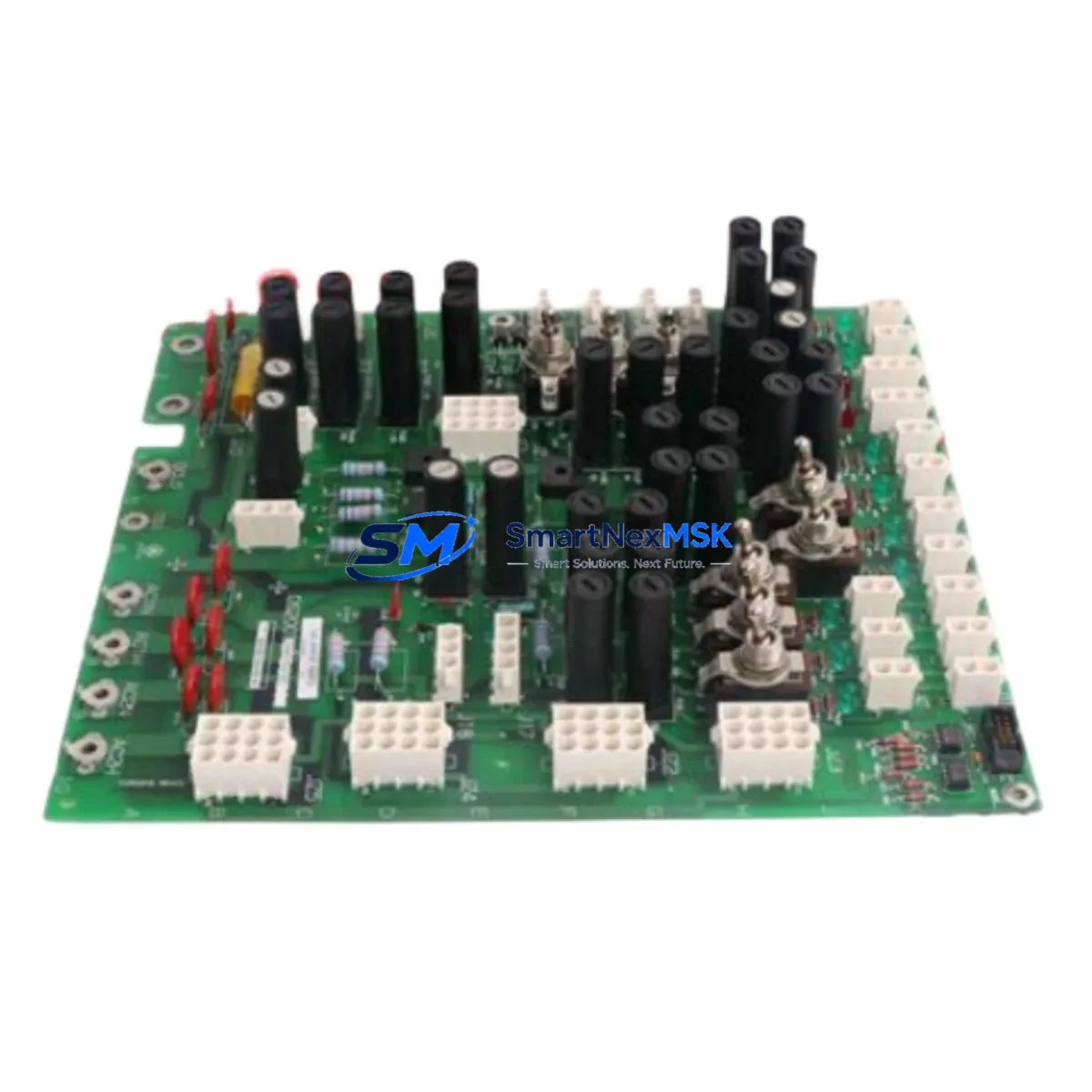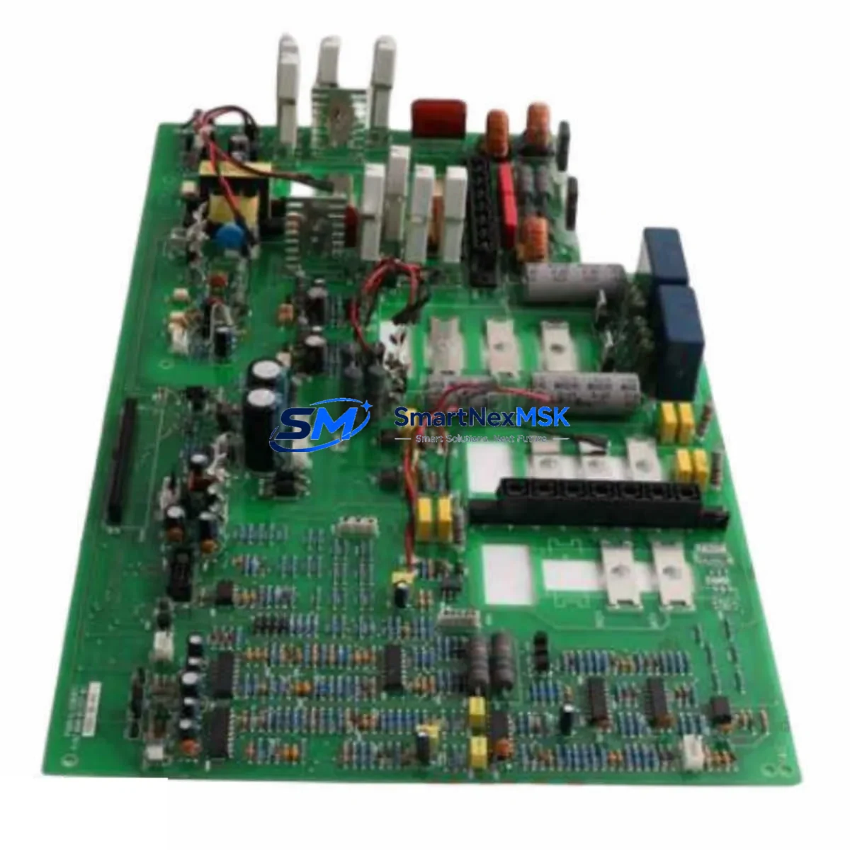
TEL E2B405/M744 Retrofit-Ready CPU PCB Card for E2B Series Control Systems
The TEL E2B405/M744 is a retrofit-ready CPU PCB card engineered for seamless integration into legacy E2B series semiconductor and industrial control systems manufactured by Tokyo Electron Limited (TEL). As original E2B405/M744 units approach end-of-life and OEM support is discontinued, this replacement module provides a validated, drop-in upgrade path that preserves existing wiring infrastructure, backplane interfaces, and control logic — minimizing engineering rework and unplanned downtime during system modernization.
Whether you are managing a planned retrofit of an aging E2B control cabinet, responding to an unplanned CPU board failure, or executing a phased migration from legacy TEL architecture to a more maintainable platform, the E2B405/M744 replacement card is stocked and ready for immediate dispatch from our Xiamen warehouse. Each unit undergoes pre-shipment functional testing and is covered by a 12-month warranty against manufacturing defects.
Upgrade Compatibility Table
| Parameter | Details |
|---|---|
| SKU / Part Number | E2B405/M744 |
| Brand / OEM | TEL (Tokyo Electron Limited) |
| Compatible Series | E2B Series, M744 Platform |
| Module Function | CPU PCB Card — Central Processing & Control Logic |
| Backplane Interface | E2B-series proprietary backplane connector; verify slot position and rack type before installation |
| Power Requirements | Confirm rack power supply capacity (typically 5 VDC / 24 VDC rails); verify against existing TEL power supply module output |
| Communication Compatibility | Compatible with E2B series communication protocols; verify fieldbus or serial link configuration (RS-232/RS-422/proprietary TEL bus) prior to commissioning |
| Installation Requirement | Direct slot replacement; no mechanical modification required for standard E2B rack configurations |
| Replacement Recommendation | Recommended as 1:1 replacement for discontinued E2B405/M744 OEM units; confirm firmware revision compatibility with system integrator |
| Commissioning Notes | Restore program backup before power-on; verify I/O module addressing and HMI screen tag mapping post-swap |
| Origin | Japan |
| Warranty | 12 Months — covers manufacturing defects; pre-shipment functional test included |
Retrofit Planning for Existing Automation Systems
A successful E2B405/M744 retrofit begins well before the replacement card arrives on-site. Engineers should start by auditing the existing control cabinet to document the current rack configuration, including the number of occupied slots, the position of I/O expansion modules, and the routing of terminal wiring to field devices. In a typical E2B series installation, the CPU card occupies a dedicated slot in the main rack, with adjacent slots populated by analog input modules, digital output modules, and — in networked configurations — a dedicated communication module handling upstream data exchange with SCADA or DCS layers.
Before removing the original E2B405/M744 board, engineers must back up the resident control program using the appropriate TEL programming software or a compatible programming cable. Failure to capture a verified program backup is the single most common cause of extended downtime during CPU board replacements. Once the backup is confirmed, document all terminal block wiring assignments, paying particular attention to 24 VDC power distribution rails, analog signal shielding, and any hardwired interlock circuits that bypass the CPU logic.
During the physical swap, inspect the backplane connector on both the rack and the replacement card for bent pins or contamination. In older E2B installations, backplane connectors may show oxidation after years of service in environments with humidity or airborne particulates — clean contacts with appropriate electronic contact cleaner before seating the new module. After installation, verify that the rack power supply module is delivering stable voltage within the specified tolerance before powering the CPU card.
Post-installation commissioning should follow a structured sequence: restore the program backup, verify module addressing for all I/O cards in the rack, confirm that HMI screen tags are correctly mapped to the new CPU’s data registers, and test each communication link — whether a serial RS-422 connection to a remote I/O station, a fieldbus segment, or a higher-level network interface. In systems where the E2B series rack communicates with external controllers or supervisory systems, verify that the communication module configuration (node address, baud rate, protocol parameters) is preserved after the CPU swap. Related components commonly involved in this process include the rack backplane assembly, the system power supply unit, digital I/O modules, analog signal conditioning cards, and the HMI operator panel connected to the control network.
Downtime Control During System Migration
Minimizing production downtime during a CPU board replacement requires a combination of advance preparation, staged testing, and a clear rollback plan. The most effective approach is to pre-configure and bench-test the replacement E2B405/M744 card in a controlled environment before the scheduled maintenance window. Where a spare rack or test bench is available, load the backed-up program, simulate I/O signals, and verify that the control logic executes correctly before the card is transported to the production floor.
During the maintenance window itself, follow a strict sequence: isolate the control system from field power, remove the failed or aging CPU card, install the replacement E2B405/M744, restore the program, and perform a controlled power-up with field outputs inhibited. Step through each output channel manually before releasing the system to automatic control. This approach protects field devices — actuators, drives, solenoid valves — from unexpected activation during the commissioning phase and allows engineers to verify that every I/O point responds correctly before resuming production.
For systems where a cold standby is not feasible, consider a phased migration strategy: maintain the original CPU card in service while preparing the replacement, and execute the physical swap during the shortest available maintenance window. In multi-rack E2B configurations, the CPU swap in the master rack does not necessarily require taking down remote I/O racks simultaneously — coordinate with the site control engineer to determine which subsystems can remain energized during the transition. Keeping detailed commissioning records — including pre-swap and post-swap I/O test results, communication link verification logs, and HMI screen validation checklists — supports both regulatory compliance and future maintenance planning.
Retrofit Support FAQ
Q1: Is the E2B405/M744 a direct drop-in replacement for the original TEL OEM part?
The E2B405/M744 replacement card is designed to match the original OEM form factor and backplane interface for standard E2B series rack configurations. Before installation, confirm the firmware revision and hardware variant of your existing system with your site integrator or TEL documentation to ensure full compatibility.
Q2: What wiring changes are required when replacing the CPU card?
In most E2B series installations, the CPU card does not carry direct field wiring — terminal connections are made at the I/O module level. The primary wiring verification task is to confirm that the rack power supply connections and any communication cable terminations (RS-232, RS-422, or proprietary TEL bus connectors) are correctly re-seated after the card swap. Document all connector positions before removal.
Q3: How do I verify communication link compatibility after the replacement?
After restoring the control program and powering up the replacement E2B405/M744, use the TEL programming software or a compatible diagnostic tool to verify that all configured communication links are active. Check node addresses, baud rates, and protocol parameters against the pre-swap configuration record. If the system includes a communication module for fieldbus or serial network connectivity, verify that the module’s configuration registers are correctly initialized by the new CPU.
Q4: What does the 12-month warranty cover, and is pre-shipment testing included?
Every E2B405/M744 replacement card is functionally tested prior to shipment to verify basic CPU operation and backplane interface integrity. The 12-month warranty covers manufacturing defects identified under normal operating conditions. It does not cover damage resulting from incorrect installation, overvoltage, or environmental conditions outside the specified operating range. Contact sales@smartnexmsk.com for warranty claims or technical support.
© 2026 SMARTNEXMSK. All rights reserved.
Original Source: https://smartnexmsk.com
Contact: sales@smartnexmsk.com | +86 18259474341