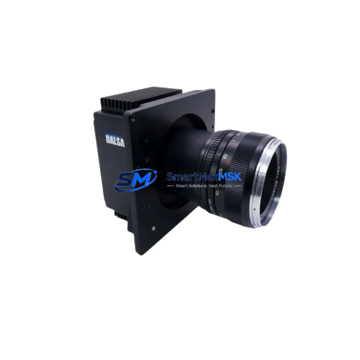
Teledyne DALSA VA2-03-C11-1 Retrofit-Ready Area Scan Camera for Genie Series Control Systems
The Teledyne DALSA VA2-03-C11-1 is a 0.3MP Color CameraLink area scan camera engineered for seamless integration into existing Genie Series machine vision systems. Whether you are replacing an end-of-life unit, upgrading a legacy inspection line, or restoring a production system after an unplanned failure, the VA2-03-C11-1 delivers a verified drop-in retrofit path with minimal reconfiguration. SMARTNEXMSK maintains ready stock of this model to support urgent replacement and planned system modernization projects worldwide.
Upgrade Compatibility Table
| Parameter | VA2-03-C11-1 Specification | Retrofit Notes |
|---|---|---|
| Resolution | 0.3MP (640 × 480) | Direct replacement for same-resolution Genie Series units |
| Color / Mono | Color (Bayer) | Confirm frame grabber supports color decoding; mono grabbers require firmware update |
| Interface | CameraLink Base | Compatible with existing CameraLink Base frame grabbers; no cable change required |
| Power Supply | 12 VDC via CameraLink connector | Verify host frame grabber or power injector output; nominal 12 V ± 10% |
| Lens Mount | C-Mount | Existing C-Mount lenses and adapters are fully reusable |
| Communication | CameraLink serial (GenICam / GigE Vision API) | Sapera LT SDK compatible; update camera descriptor file if required |
| Trigger Input | Opto-isolated, TTL compatible | Existing trigger wiring and PLC output modules are compatible without rewiring |
| Installation | Standard 30 mm mounting holes | Existing brackets and mounting hardware are reusable |
| Replacement Recommendation | Direct drop-in for VA2-03-C11-1 and compatible Genie variants | Confirm firmware version with Sapera LT Device Manager before go-live |
| Warranty | 12-Month Warranty | Covered from date of shipment; includes functional verification and burn-in test |
Retrofit Planning for Existing Automation Systems
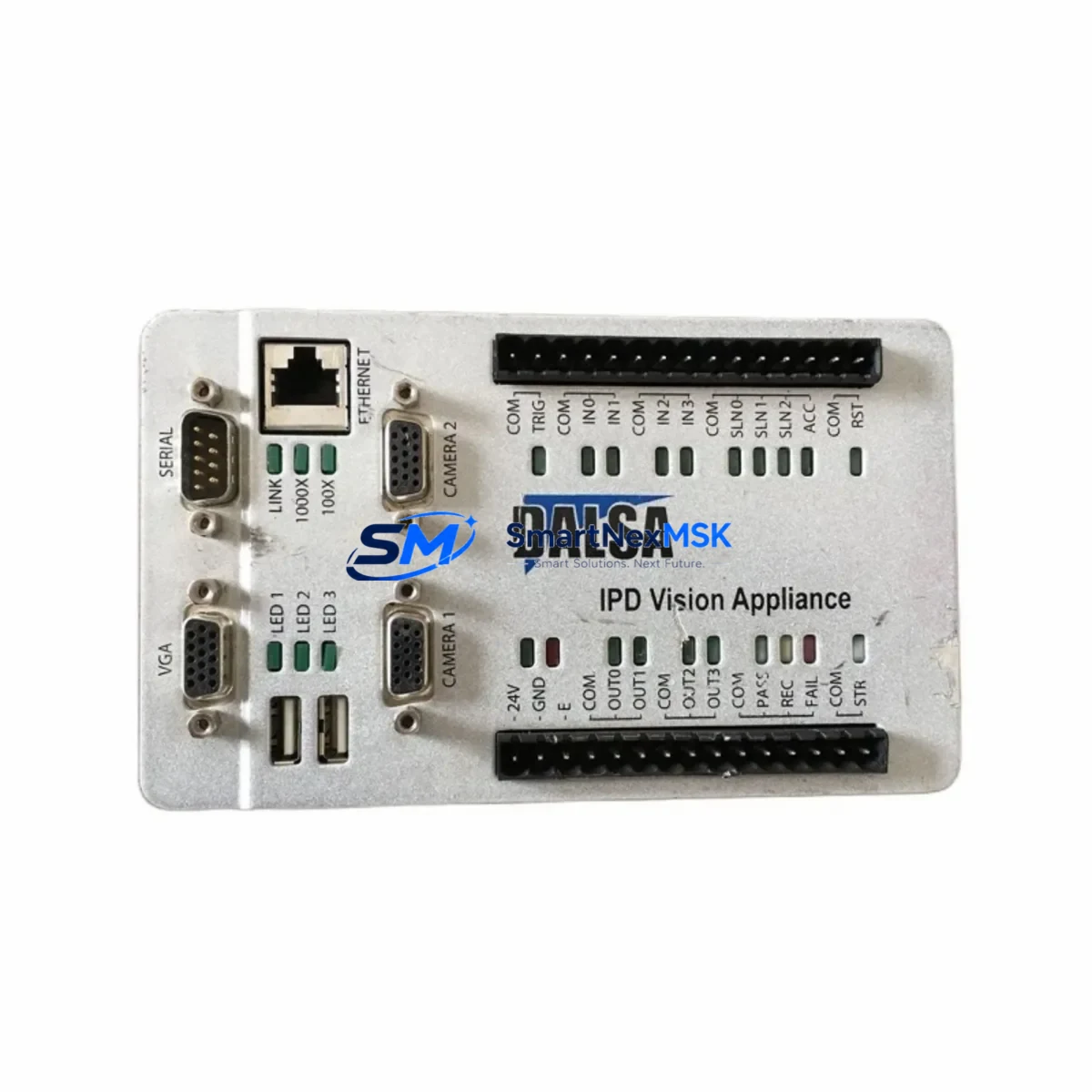
Integrating the VA2-03-C11-1 into a running production environment requires a structured approach to avoid configuration drift and unplanned downtime. The camera communicates over a CameraLink Base interface, which means your existing frame grabber — such as a Teledyne DALSA Xcelera-CL PX4 or compatible third-party CameraLink acquisition board — remains fully usable without hardware replacement. Before installation, verify that the frame grabber firmware and Sapera LT SDK version support the VA2-03-C11-1 camera descriptor file. In most Genie Series deployments, the camera descriptor (*.ccd or *.cca file) can be updated through the Sapera LT Device Manager without modifying the host application.
On the mechanical side, the VA2-03-C11-1 uses a standard C-Mount lens interface, so existing optics, extension tubes, and lighting assemblies can be retained. Confirm the back focal distance if the original unit used a CS-Mount adapter, as this will affect focus calibration after installation. The camera’s 30 mm mounting pattern is consistent across the Genie Series, allowing direct reuse of existing camera brackets and enclosure mounts without machining or modification.
For trigger and I/O wiring, the VA2-03-C11-1 accepts opto-isolated TTL trigger signals, which are compatible with standard PLC digital output modules used in Siemens S7, Allen-Bradley ControlLogix, and Mitsubishi MELSEC control architectures. No rewiring of the trigger circuit is required in typical Genie Series retrofit scenarios. If the system uses a dedicated I/O breakout board or terminal block assembly connected to the frame grabber’s I/O port, these components remain fully compatible.
Power delivery is handled through the CameraLink connector at 12 VDC. Confirm that the frame grabber or external power injector provides stable 12 V ± 10% under load. In systems where multiple cameras share a common power rail — for example, in multi-camera inline inspection stations — verify that the power supply capacity is sufficient after adding or replacing units. A 24 VDC to 12 VDC step-down module or a dedicated camera power supply such as those used alongside Cognex In-Sight systems or Keyence CV-X series controllers may be required in mixed-platform environments.
If the production line uses an HMI panel — such as a Siemens TP700 Comfort, Weintek MT8000, or Proface GP4000 series — confirm that the vision inspection result outputs (pass/fail signals, measurement data) are mapped correctly after camera replacement. In most cases, the PLC ladder logic and HMI screen bindings do not require modification if the camera replacement is performed at the same resolution and interface type. However, if the original camera used a proprietary vision controller with embedded logic, a brief re-teach of the inspection tool parameters in the vision software will be necessary.
Downtime Control During System Migration
Minimizing production downtime during a camera replacement is a primary concern for any retrofit project. SMARTNEXMSK recommends a pre-staged swap approach: configure and verify the replacement VA2-03-C11-1 on a bench setup before removing the original unit from the line. Using Sapera LT CamExpert, confirm that the camera streams live images at the correct resolution, frame rate, and color format before installation. Save the verified camera configuration as a named preset so it can be loaded immediately after physical installation.
During the physical swap, document the original cable routing, trigger wiring, and lens position before disconnection. Label all connectors and take reference photographs of the installation. The CameraLink MDR-26 cable should be inspected for pin damage before reuse, as connector wear is a common source of intermittent faults in legacy systems. If the cable shows signs of wear, replace it with a new CameraLink Base cable of the same length to avoid signal integrity issues.
After installation, perform a live image verification in the vision application before re-enabling the production trigger. Confirm that the inspection tool thresholds, region of interest boundaries, and output signal timing are within specification. In systems where the vision result feeds directly into a PLC-controlled reject mechanism or conveyor divert gate, run a manual trigger cycle to verify end-to-end signal flow before returning the line to automatic mode. This staged verification process typically allows a complete camera replacement to be completed within a single planned maintenance window, with no modification to the existing PLC program or HMI configuration.
For systems that cannot tolerate any unplanned interruption, SMARTNEXMSK can provide a pre-tested and pre-configured VA2-03-C11-1 unit with your specific camera settings pre-loaded, reducing on-site configuration time to under 15 minutes in most standard Genie Series installations.
Retrofit Support FAQ
Q1: Is the VA2-03-C11-1 a direct replacement for my existing Genie Series camera?
A: Yes. The VA2-03-C11-1 is a direct form-fit-function replacement for same-resolution Genie Series CameraLink models. The C-Mount lens interface, 30 mm mounting pattern, CameraLink Base connector, and opto-isolated trigger input are consistent across the Genie Series product family. Confirm the camera descriptor file version in Sapera LT Device Manager after installation to ensure full software compatibility.
Q2: Do I need to modify my PLC program or HMI screens after replacing the camera?
A: In most cases, no. If the replacement camera operates at the same resolution and interface type as the original, the PLC output signals, HMI display bindings, and inspection result mappings remain valid. A brief re-teach of vision tool parameters may be required if the original camera used embedded inspection logic rather than a host-based vision application.
Q3: What pre-shipment testing is performed on each unit?
A: Every VA2-03-C11-1 unit shipped by SMARTNEXMSK undergoes functional power-on verification, live image streaming confirmation, trigger response testing, and CameraLink interface integrity check before dispatch. Units are shipped with a test report and are covered by a 12-month warranty from the date of shipment.
Q4: What is the lead time and warranty coverage?
A: SMARTNEXMSK maintains ready stock of the VA2-03-C11-1 for same-day or next-business-day dispatch. Standard international shipping lead time is 3–7 business days depending on destination. All units are covered by a 12-month warranty covering manufacturing defects and functional failures under normal operating conditions. Expedited shipping and pre-configured units are available on request.
© 2026 SMARTNEXMSK. All rights reserved.
Original Source: https://smartnexmsk.com
Contact: sales@smartnexmsk.com | +86 18259474341