Uniop eTOP133C-0050 Spare for eTOP Series Automation: Spare Replacement & Industrial Downtime Risk Control
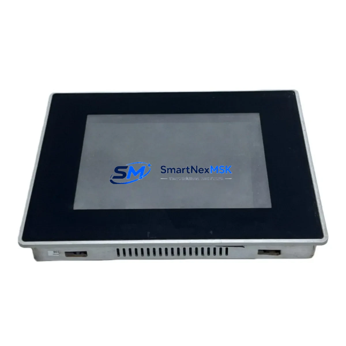
The Uniop eTOP133C-0050 is a color touchscreen HMI operator panel from the eTOP Series, widely deployed in industrial automation control cabinets across manufacturing, process control, and machine tool environments. When this panel fails or reaches end-of-service life, rapid replacement is critical to restoring production continuity. SMARTNEXMSK maintains verified stock of the eTOP133C-0050 as an original spare, pre-tested and ready for immediate dispatch to minimize unplanned downtime.
Maintenance engineers and procurement teams working with Uniop eTOP Series systems understand that HMI panel failures are rarely isolated events. A failed eTOP133C-0050 often signals stress across adjacent components in the same control cabinet — power supply rails, communication interfaces, and I/O wiring harnesses all warrant inspection during any panel replacement procedure. Our supply chain is structured to support both emergency single-unit replacements and planned bulk spare procurement for long-term maintenance contracts.
Spare Maintenance Table
| Parameter | Specification |
|---|---|
| Part Number / SKU | eTOP133C-0050 |
| Brand | Uniop |
| Series | eTOP Series |
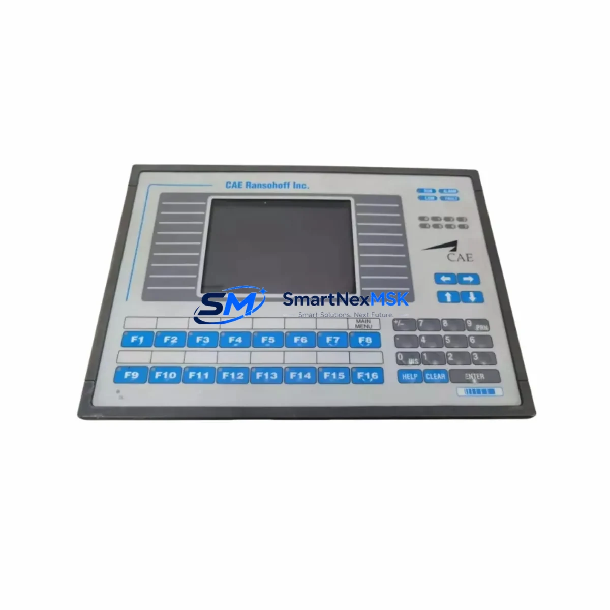
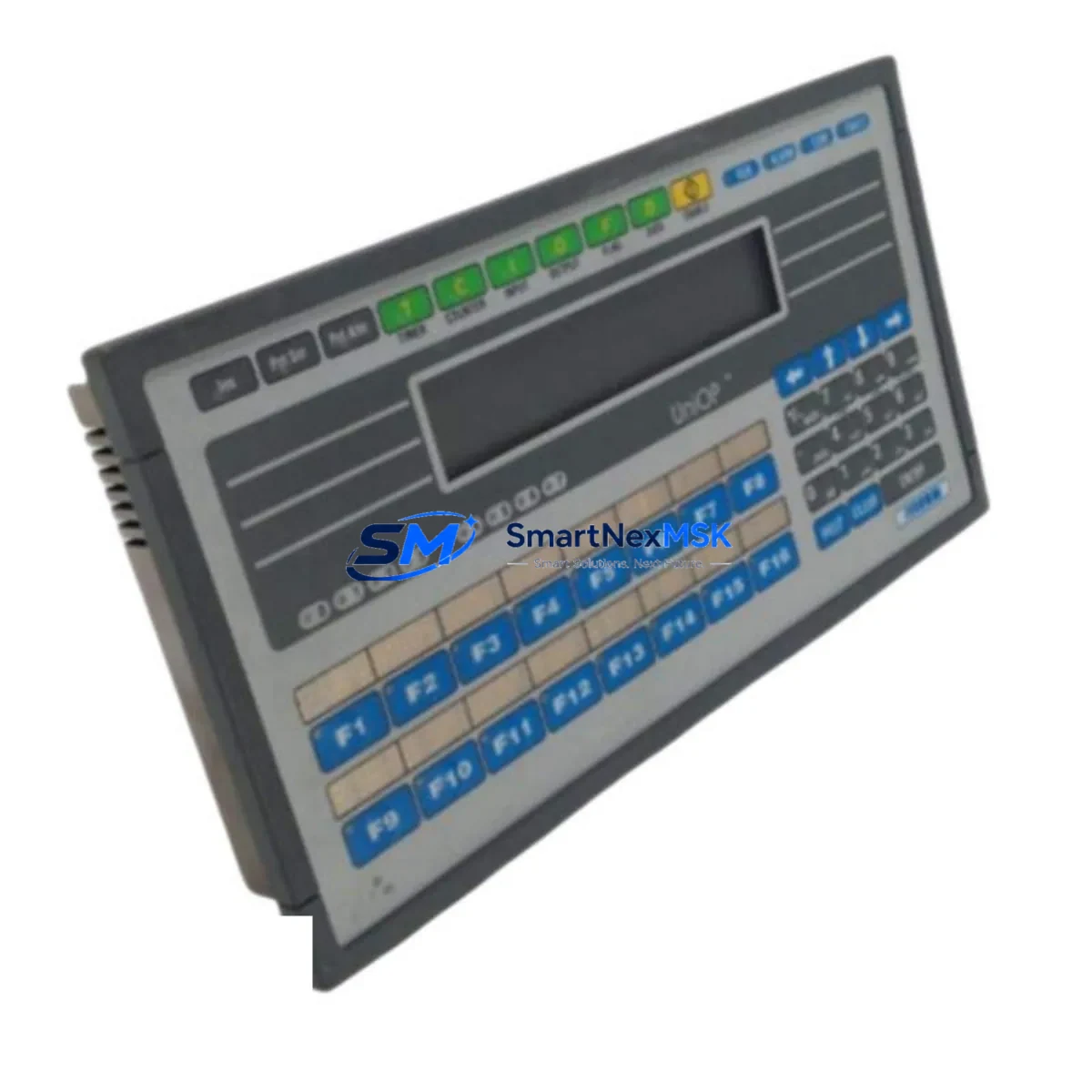
| Product Type | HMI Color Touchscreen Operator Panel |
| Display | Color TFT LCD Touch Panel |
| Origin | Italy |
| Compatibility | Uniop eTOP Series control systems; compatible with standard 24VDC panel power supplies and RS-232 / RS-485 / Ethernet communication interfaces |
| Installation | Panel-mount; standard cutout dimensions per eTOP Series specification |
| Application Environment | Industrial automation, machine tool control, process manufacturing, OEM control cabinets |
| Maintenance Recommendation | Inspect power supply, communication cables, and I/O terminal blocks during replacement; verify firmware version compatibility before commissioning |
| Condition | Original spare; tested before shipment |
| Warranty | 12 Months |
| Lead Time | In stock — ships within 1–3 business days |
Maintenance Planning for Continuous Operation
Replacing the eTOP133C-0050 is a structured procedure that goes beyond swapping the panel itself. Experienced maintenance engineers treat an HMI replacement as an opportunity to audit the entire operator station and associated control cabinet. During a planned or emergency replacement of this Uniop eTOP Series panel, the following components should be inspected or replaced as part of a comprehensive maintenance cycle:
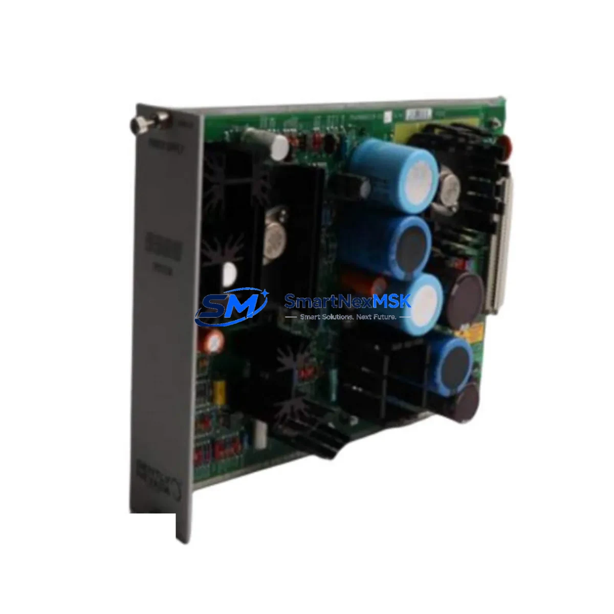
- 24VDC Panel Power Supply — Verify output voltage stability and ripple. A degraded power supply is a common root cause of HMI display faults and communication dropouts. Units such as Uniop-compatible 24VDC DIN-rail power supplies should be load-tested during the maintenance window.
- RS-232 / RS-485 Communication Cables — Inspect shielding integrity, connector crimps, and cable routing. The eTOP133C-0050 relies on serial communication to the PLC or DCS controller; damaged cables cause intermittent communication faults that are difficult to diagnose remotely.
- Ethernet Communication Module — If the eTOP133C-0050 is networked via Ethernet, inspect the RJ45 connector, patch cable, and managed switch port for link errors or CRC faults. Uniop eTOP Series Ethernet driver compatibility with the connected PLC should be re-confirmed after any firmware update.
- PLC CPU or Communication Processor — Confirm the connected PLC (e.g., Siemens S7-300/400, Mitsubishi Q Series, or equivalent) is communicating correctly after panel replacement. A firmware or driver mismatch between the new HMI and the PLC can prevent successful commissioning.
- I/O Terminal Blocks and Wiring Harnesses — Check terminal torque, insulation condition, and labeling. Loose terminals in the operator station can cause signal noise that manifests as HMI screen glitches or false alarms.
- Signal Isolators — Analog signal isolators between field instruments and the control system should be verified for correct output range. A failed isolator can corrupt process values displayed on the eTOP133C-0050, leading to misdiagnosis of the HMI itself.
- Relay Output Modules — Inspect relay coils and contacts associated with operator commands issued from the HMI. Worn relay contacts cause intermittent output failures that are often incorrectly attributed to HMI software faults.
- Fuse Holders and Circuit Protection — Verify fuse ratings and continuity on the 24VDC supply circuit feeding the HMI panel. Thermal cycling can cause fuse holder contacts to oxidize, creating intermittent power interruptions.
- Backplane and Rack Assembly — In rack-mounted control systems, inspect the backplane bus connectors for oxidation or mechanical damage. A compromised backplane can cause erratic behavior across multiple modules, including the HMI communication interface card.
- UPS / Battery Backup Unit — Confirm the uninterruptible power supply serving the control cabinet is within its service life. A failing UPS battery can cause voltage sags during load switching that damage sensitive HMI electronics over time.
Stocking the eTOP133C-0050 as a dedicated spare — alongside a matched 24VDC power supply unit and a set of pre-terminated RS-485 communication cables — reduces mean time to repair (MTTR) from hours to minutes in emergency scenarios. Procurement engineers managing multi-site maintenance contracts should consider holding a minimum of two units per site where the eTOP Series HMI is deployed as the primary operator interface.
Site Replacement Workflow
The eTOP133C-0050 is a direct replacement for aging or failed units within the Uniop eTOP Series product family. The replacement workflow is designed to minimize control system downtime and maintain full compatibility with existing PLC programs and HMI project files:
- Pre-Replacement Backup — Before removing the failed panel, back up the HMI project file from the existing unit if it is still partially functional. If the panel is completely unresponsive, retrieve the project file from the engineering workstation or SCADA archive.
- Power Isolation — Isolate the 24VDC supply to the HMI panel using the dedicated circuit breaker or fuse. Follow LOTO (Lockout/Tagout) procedures as required by site safety policy.
- Panel Removal and Inspection — Remove the failed eTOP133C-0050 from the panel cutout. Inspect the cutout gasket, mounting clamps, and rear connector for damage. Clean the cutout area before installing the replacement unit.
- Replacement Installation — Install the new eTOP133C-0050, reconnect all communication and power cables, and verify connector seating. Restore 24VDC power and confirm the panel boots to the main menu.
- Project File Download — Download the backed-up HMI project file to the replacement panel using the Uniop programming software. Verify all screens, alarms, and communication tags are functioning correctly before releasing the system.
- Functional Verification — Conduct a full I/O test from the HMI, confirm PLC communication is stable, and verify all operator commands produce the expected machine responses before returning the system to production.
This workflow applies equally to planned maintenance replacements and emergency breakdown scenarios. Having a pre-configured spare eTOP133C-0050 with the project file pre-loaded reduces commissioning time to under 30 minutes in most installations. For legacy systems where the original Uniop programming software version is no longer available, SMARTNEXMSK technical support can advise on compatible software versions and driver packages.
Spare Parts Support FAQ
Q1: Is the eTOP133C-0050 still available as a new original spare, or only as a refurbished unit?
SMARTNEXMSK supplies the eTOP133C-0050 as an original spare sourced from authorized distribution channels. Each unit undergoes functional testing before shipment. Where new stock is available, it is supplied as new; where the model has been superseded, we supply verified original units with full 12-month warranty coverage.
Q2: How do I confirm compatibility between the eTOP133C-0050 replacement and my existing PLC or control system?
Compatibility is determined by the communication protocol (RS-232, RS-485, or Ethernet), the PLC driver supported by the Uniop eTOP Series firmware, and the HMI project file version. Provide your existing PLC model and HMI project software version when placing your order, and our technical team will confirm compatibility before shipment.
Q3: What is included in the 12-month warranty, and how does the claims process work?
The 12-month warranty covers manufacturing defects and functional failures under normal operating conditions. It does not cover damage caused by incorrect installation, overvoltage, or environmental factors outside the rated specification. To initiate a warranty claim, contact sales@smartnexmsk.com with the order number, fault description, and photographic evidence. Replacement units are dispatched after fault verification.
Q4: Can I order multiple units for long-term spare parts inventory, and what lead times apply?
Yes. SMARTNEXMSK supports bulk spare procurement for maintenance contracts and long-term inventory programs. In-stock units ship within 1–3 business days. For quantities exceeding standard stock levels, lead times are confirmed at the time of order. Volume pricing is available — contact sales@smartnexmsk.com for a formal quotation.
© 2026 SMARTNEXMSK. All rights reserved.
Original Source: https://smartnexmsk.com
Contact: sales@smartnexmsk.com | +86 18259474341